




fig13
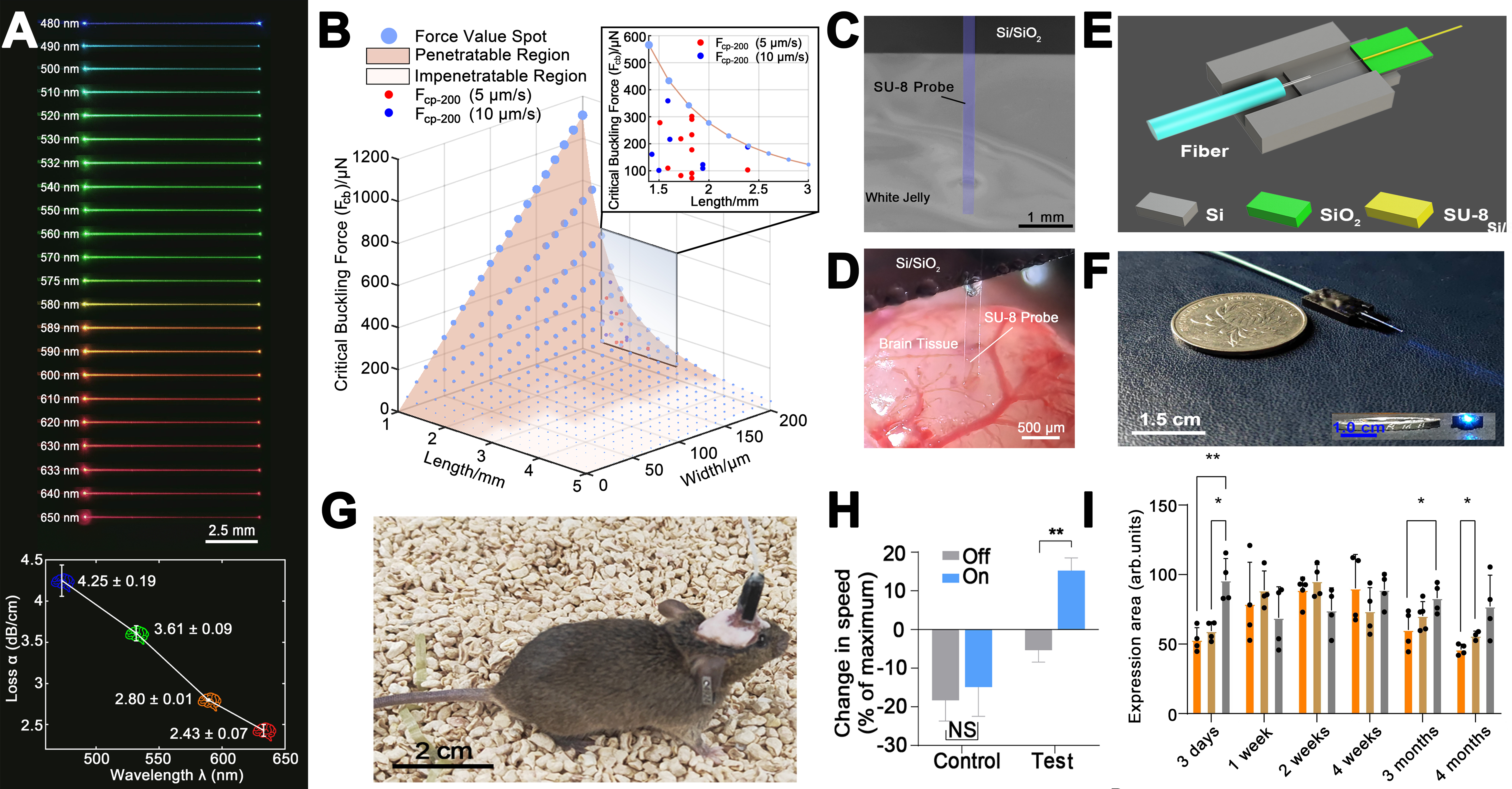
Figure 13. Flexible SU-8 waveguide optogenetic probe[134]: (A) the propagation loss of SU-8 waveguide at visible region; (B) Implant mechanical model with experimental data; Insertion of the flexible waveguide probe into the phantom brain (C) white jelly, (D) actual brain tissue; (E) Schematic diagram of packaging scheme; (F) Photograph of a well-encapsulated flexible waveguide probe; (G) Photograph of mice recovering from the probe implantation surgery; (H) Behavioral experiment; (I) Inflammatory experiment. NS is non-significance, meaning that there is no difference between the two groups. *P < 0.05, **P < 0.01. This figure is adapted from Ref.[134]. Copyright © 2024 Elsevier.