




Designable transverse thermoelectricity through interlayer thermal coupling for conformal heat harvesting
 0
Abstract
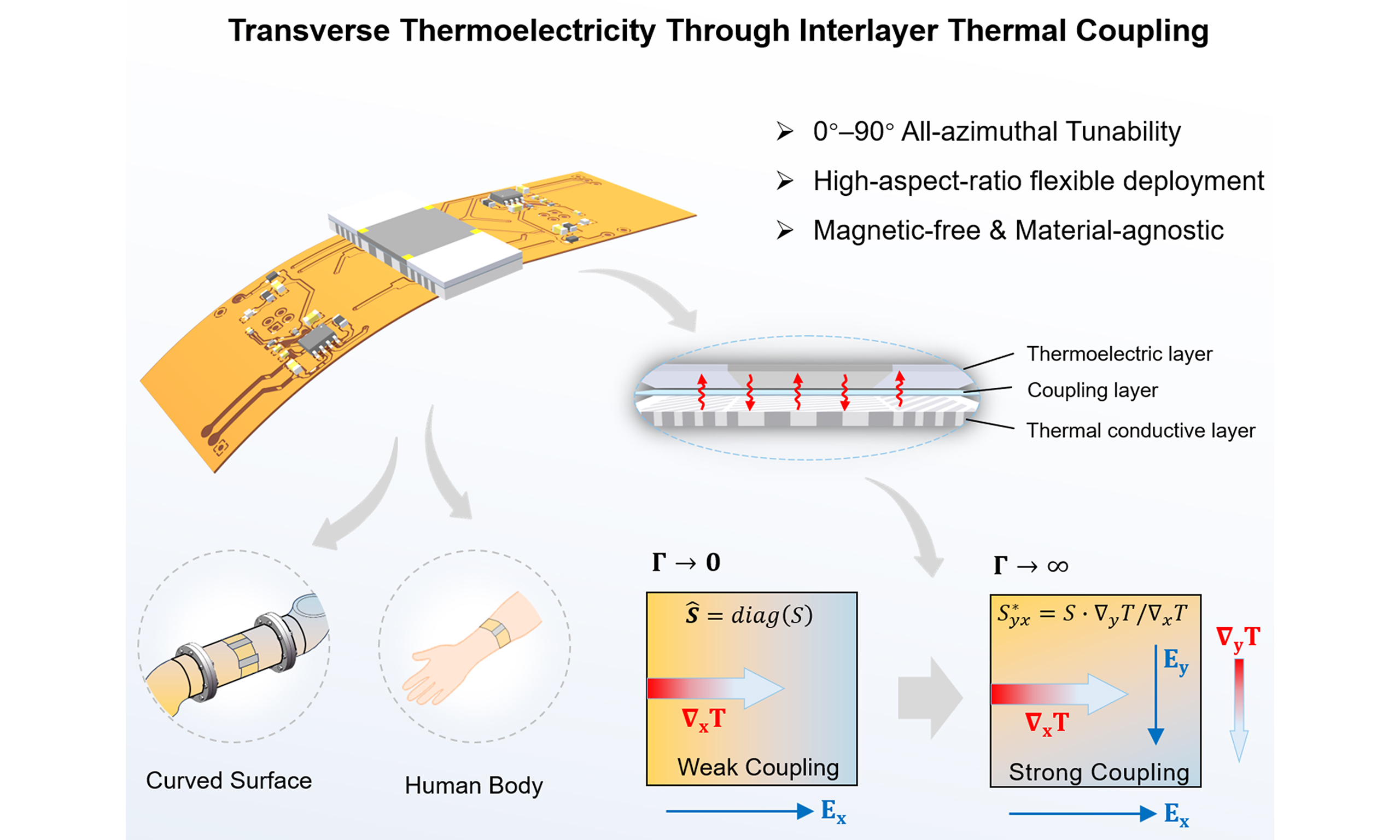
Transverse thermoelectric conversion is developed to break the inherent restrictions of traditional thermoelectrics regarding integration, scaling and geometric adaptability. Although the strategy intrinsically separates heat flow and electric current, practical realization is highly dependent on intrinsic materials with off-diagonal Seebeck tensors or strong external magnetic fields. Here, we propose an interlayer thermal coupling mechanism for decoupling the thermoelectric field. The spatial double-layer configuration consisting of a lower thermal layer for tailoring heat flux and an upper thermoelectric layer, enables interlayer heat exchange while maintaining electrical insulation, thereby inducing an equivalent material-agnostic transverse thermoelectric response. The key behavior is revealed by a dimensionless coupling parameter, enabling all-azimuthal engineering. We directly visualize the reconfigurable multi-field manipulation induced by the interlayer thermal-coupling effect of the upper thermoelectric layer. The resulting thermal field yields magnetic-free tailored transverse thermoelectric flow within an extensible plane, which breaks the constraint of cascading thermoelectric configurations. Furthermore, by integrating the planar device, we demonstrate a conformal harvesting architecture that enables flexible deployment and reconfigurable multi-dimensional energy harvesting. Our work opens a route towards material-agnostic control of heat and charge, which enriches design paradigms and integration modes of thermoelectric devices, demonstrating remarkable potential for application in scalable multi-dimensional thermoelectric systems.
Keywords
INTRODUCTION
Thermoelectric conversion provides a solid-state route for harvesting energy from waste heat and renewable sources[1-3], enabling direct heat-to-electricity transduction without moving parts, mechanical noise, or greenhouse-gas emissions. State-of-the-art modules are predominantly built on cascading architectures of alternating p-type and n-type legs, which require segmented electrode interconnects and rigid mechanical frames, inherently limiting in-plane scalability and conformal deployment on curved surfaces[4,5]. Transverse thermoelectricity naturally decouples the directions of heat flow and electric current[6,7], eliminating the need for alternating p-n junctions and complex electrode interconnects, thereby endowing the architecture with excellent in-plane deployment and conformal adaptability[8-10]. To translate this mechanism into practical devices, one avenue relies on exotic materials with intrinsic off-diagonal Seebeck tensors, such as ferromagnets or topological compounds, facing material, characteristic, and scalability challenges[11-13]. Alternatively, artificially tilted multilayer structures offer another geometry-based route, yet the heat-to-current angle is typically locked near 45° and the design is severely constrained by interlayer compatibility[14-16]. Magnetic thermoelectric effects provide another pathway but require intense external magnetic fields that conflict with the lightweight, portable goals of practical energy harvesting[17,18].
To transcend the limitations outlined above, artificial structure-based physical-field engineering has emerged as a transformative alternative[19-21]. Structural configuration and geometric design achieve precise control of energy transport pathways, breaking angular restrictions and enabling full-range energy-flow manipulation[22-24]. When extended to thermoelectric architectures, such geometric engineering achieves magnetic-free transverse energy transport through purely structural means[25,26]. Nevertheless, these advances remain fundamentally constrained by two persistent challenges. First, the thermal-field engineering structure and the thermoelectric conversion layer are co-planar, creating inherent electrical impedance[27,28]. Second, thermal and electric fields are cooperatively manipulated within a single functional layer, so that local tailoring in thermotics directly reshapes electrical fields and current paths, precluding independent optimization of heat and charge transport pathways[29,30]. This dual challenge demands a fundamentally new design paradigm that physically separates thermal field engineering from thermoelectric conversion, liberating each layer from the impedance constraints of the other and granting independent design freedom to thermal geometry and electrical response.
Here, we propose a bilayer thermoelectric architecture that physically separates thermal field engineering from thermoelectric conversion through interlayer thermal coupling, in which an oblique thermal field is deliberately constructed in a lower anisotropic thermal conductive layer and transmitted to an upper isotropic thermoelectric layer through a thin coupling interlayer, thereby inducing a magnetic-free, effective transverse thermoelectric response without altering the intrinsic properties of the thermoelectric material
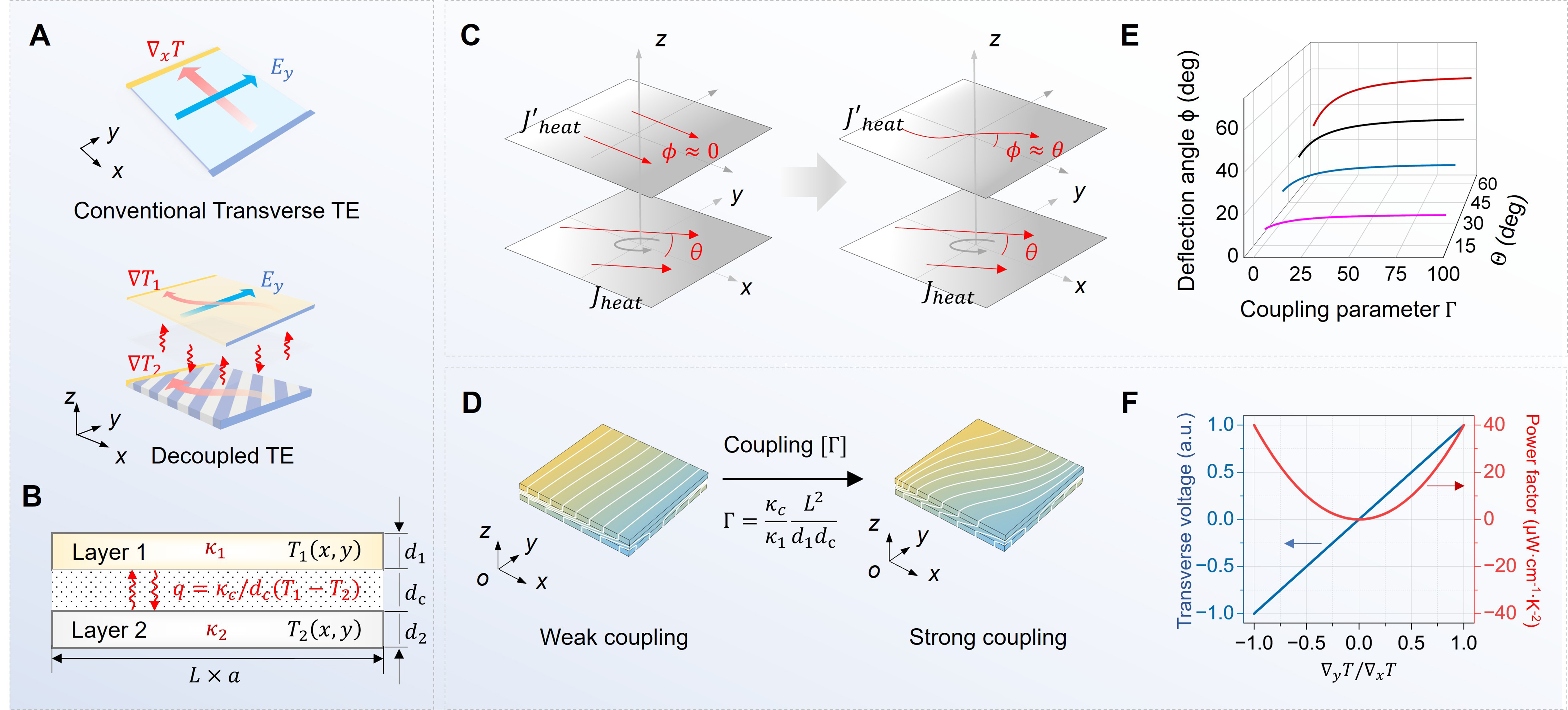
Figure 1. Principle of spatially decoupled transverse thermoelectric response. (A) Comparison between conventional transverse TE elements (top) and the proposed decoupled TE architecture (bottom); (B) Schematic of a two-layer thermal diffusion system model. The thermal conductivities and thicknesses of Layer 1 and Layer 2 are denoted as κ1, κ2 and d1, d2, with their corresponding temperature fields defined as T1, T2. A thermally coupled interlayer with equivalent thermal conductivity κc and thickness dc exists between the two layers; (C) Schematic illustration of the 3D thermal coupling mechanism: the lower layer with thermal deflection angle θ drives the upper layer to present continuously adjustable oblique angles that shift from ϕ = 0 to ϕ ≈ θ; (D) The effect of the dimensionless coupling parameter Γ =
EXPERIMENTAL
Materials and reagents
Polydimethylsiloxane (PDMS, Sylgard 184) was purchased from Dow Corning Co., Ltd. Polyimide (PI) films and polytetrafluoroethylene (PTFE) films were commercially obtained from RAYITEK Hi-Tech Film Co., Ltd. Silica aerogel ultrathin films were purchased from Nanuo Technology Co., Ltd. Thermal rubbers with different thermal conductivities were purchased from Kafuter New Materials Technology Co., Ltd. Bi2Te3-based thermoelectric plates (15 mm × 15 mm × 1 mm) were purchased from Quanzhou Qijin New Material Co., Ltd. and characterized before assembly [Supplementary Figure 1]. Flexible printed circuit (FPC) boards were custom-fabricated by JLCPCB (Shenzhen Jialichuang Technology Co., Ltd.) and adopted as the circuit substrates. Anhydrous ethanol was purchased from Sinopharm Chemical Reagent Co., Ltd. Low-temperature curing conductive silver paste was purchased from Kaitesen Co., Ltd. The detailed parameters of the films and the corresponding coupling parameters are listed in Supplementary Table 1.
Fabrication of flexible thermal metamaterial devices
The Al2O3 skeleton was fabricated by stereolithography (SLA) 3D printing using a photosensitive resin mixed with high-purity alumina powder, followed by sintering at 1,400 °C for 4 h to obtain a tilted multilayered framework. The skeleton was regionally infused with silicone rubbers of different thermal conductivities according to the designed lamination configuration. The composite was vacuum-degassed for 30 min to remove residual air bubbles and fully cured at 80 °C for 24 h. Detailed structural specifications and parameters of all thermal conductive layers are summarized in Supplementary Table 2. To prepare the Bi2Te3 thermoelectric plate for electrode fabrication, the sample surface was sequentially polished with fine sandpaper and briefly etched in 5% diluted hydrochloric acid to remove native oxide layers, then rinsed with anhydrous ethanol and dried naturally. Four nickel pads (1 mm × 1 mm) were evaporated onto the corners of the processed Bi2Te3 plate as diffusion barriers; copper leads were subsequently soldered and reinforced with conductive silver paste, followed by thermal curing at 80 °C for 2 h. The bilayer thermoelectric chip was assembled by sequentially stacking the tilted thermal layer, an interchangeable coupling film, and the processed Bi2Te3 thermoelectric plate. The peripheral gaps were filled with uncured PDMS and cured at
The thermal measurement platform comprised a positive temperature coefficient (PTC) heating plate and a Peltier cooler positioned on the left and right sides, respectively, to establish a one-dimensional heat flow along the x-direction[31]. Two wedge-shaped copper blocks were machined and inserted between the heat source/cold sink and the sample to concentrate heat transfer and ensure uniform thermal contact. The hot and cold terminal temperatures were monitored by K-type thermocouples and stabilized by a PID temperature controller to maintain a constant temperature difference across the device.
Finite element simulation
The finite-element simulations were performed using COMSOL Multiphysics 6.2. The lower thermal layer was modeled as an anisotropic medium with a uniform off-diagonal thermal conductivity tensor determined by equivalent medium theory[32]. Heat convection, radiative heat loss, and interlayer thermal contact resistance were neglected. The temperatures of the hot side and cold side were set as Th = 353 K and Tc =
Mechanical characterization
Mechanical durability of the flexible bilayer devices was evaluated through cyclic bending tests at a fixed radius of 50 mm and static bending tests at various radii down to 20 mm. Cross-sectional micrographs before and after 150 bending cycles were acquired using a stereomicroscope (Olympus SZX16) to assess interfacial integrity.
Thermal and electrical characterization methods
The interlayer coupling strength was varied by replacing the coupling layer material, while the temperature difference was precisely regulated by a temperature control driver board. Thermal measurements were performed using an infrared camera (Fotric 287+) to capture the surface temperature distribution, and the acquired data were imported into OriginPro 2024 for subsequent processing, including the plotting of isotherms and temperature contour maps with color bars. Electrical measurements were conducted by a two-pair shorting method: corresponding electrodes were shorted to measure transverse and longitudinal thermoelectric voltages. Reference electrodes were connected through a preamplifier (100×), and the voltage and current were recorded by a 5½-digit digital multimeter (Keysight U3606A). Each data point was measured five times (n = 5) and averaged. Error bars in the figures denote the standard deviation (SD) of the five repeated measurements. Photographs and circuit wiring diagrams of the voltage measurement system are provided in Supplementary Figure 2. The optical image of the experimental setup for characterizing the transverse thermoelectric performance of the flexible device is shown in Supplementary Figure 3.
Thermoelectric conversion efficiency evaluation
The conversion efficiency η was evaluated by the direct heat-balance method. The maximum output power Pmax was extracted from the measured current–voltage characteristics under matched-load conditions. The input thermal power Qin was evaluated via Fourier’s law from the longitudinal temperature gradient |∂T/∂x| measured along the edge of the upper thermal conductive filling, where the heat flux is predominantly horizontal. The conversion efficiency follows as η = Pmax/Qin.
RESULTS AND DISCUSSION
Theoretical framework of transverse thermoelectricity via interlayer thermal coupling
Consider a bilayer system stacked along the z-direction with a temperature difference between high temperature Th and low temperature Tc applied along the x-direction, and the planar dimension of the system is L × a [Figure 1B]. The lower layer (Layer 2) of thickness d2 is an anisotropic thermal conductor with an off-diagonal thermal conductivity tensor κ2, while the upper layer (Layer 1) of thickness d1 is an isotropic thermoelectric layer with scalar thermal conductivity κ1. The two layers exchange heat through a thin coupling layer of thickness dc and equivalent thermal conductivity κc. The geometric configuration of this bilayer thermal coupling system is illustrated in Supplementary Figure 4. Under steady-state conditions and neglecting the through-thickness temperature gradient within each layer [Supplementary Figure 5]. The governing heat balance equations read[33]:
where T1 and T2 denote the temperature fields of the upper thermoelectric layer and the lower conductive layer, respectively. The temperature distribution within the lower layer rotates clockwise by an angle θ about the z-axis to form an inclined thermal field [Figure 1C]. The substantial thermal conductivity mismatch between the two layers drastically suppresses thermal feedback from the thermoelectric layer to the lower thermal layer. Accordingly, the thermal field of the lower layer is simplified as a predefined oblique field: T2(x,y) = T0 -
where the dimensionless coupling parameter Γ = κcL2/κ1d1dc represents the coupling strength and β = a/L refers to the width-to-length ratio. Physically, Γ describes the degree of interlayer thermal coupling, defined as the ratio of the characteristic in-plane thermal resistance of the upper layer L2/κ1d1 to the coupling layer thermal resistance dc/κc that governs heat exchange between the two layers.
Under adiabatic lateral boundary conditions (∂τ/∂η = 0 at η = ±1/2) and longitudinal Dirichlet boundary conditions (τ = ±1/2 at ξ = ±1/2), the analytical solution is obtained via separation of variables [Supplementary Note 1]:
where λn =
Under this oblique thermal excitation, the originally isotropic upper-layer thermoelectric material exhibits an effective anisotropic transport behavior. Within the linear Onsager framework[36], denoting the longitudinal and transverse temperature differences across the upper layer as ΔTx and ΔTy, respectively, which can be evaluated from the analytical temperature field as: ΔTx =
where S is the intrinsic Seebeck coefficient. Notably, the off-diagonal component Syx* = S·ΔTy/ΔTx is not an intrinsic material property, but an extrinsic response purely induced by the interlayer geometric thermal coupling[8,25]. Consequently, the effective transverse power factor and figure of merit obey [Supplementary Note 2]:
Here PF0 = S2σ and ZT0 = S2σT/κ1 are the intrinsic power factor and figure of merit, respectively, and σ is the electrical conductivity. Notably, ZT0 reflects only the intrinsic properties of the upper thermoelectric layer; the influence of the lower and coupling layers is captured by the transverse-to-longitudinal temperature ratio ΔTy/ΔTx rather than by modifying ZT0 itself. The above results demonstrate a hierarchical amplification mechanism: the off-diagonal Seebeck coefficient Syx* is activated linearly by the transverse-to-longitudinal temperature ratio ΔTy/ΔTx, while the transverse power factor and figure of merit are amplified quadratically by the same ratio. As plotted in Figure 1F, the blue straight line confirms linear transverse voltage output over ΔTy/ΔTx ∈ [-1,1], and the symmetric red parabola reflects quadratic power-factor variation. By tuning both the interlayer coupling parameter Γ and the thermal deflection angle θ of the lower thermal layer, the gradient ratio can be set to arbitrary values within the range [-1,1], enabling flexible manipulation of transverse thermoelectric output performance. This mechanism creates an innovative design route for reconfigurable flexible thermoelectric devices.
Numerical simulation of interlayer thermal coupling
To validate the theoretical framework, we performed finite-element simulations in COMSOL Multiphysics with preset parameters matching the analytical model: L = 15 mm, a = 15 mm, d1 = dc = d2 = 1 mm, θ = 45°, κ1 = 2.25 W/(m·K), κ2 =30 W/(m·K), Th = 353 K and Tc = 293 K. The bilayer geometry is illustrated in Figure 2A. As a reference, the uncoupled upper layer (Γ → 0) exhibits a purely longitudinal temperature distribution Tref with isotherms perpendicular to the x-axis. The dimensionless coupling parameter Γ = κcL2/κ1d1dc can be decomposed into two independent factors: L2/κ1d1, an intrinsic structural factor determined by geometry and upper-layer thermal conductivity, and κc/dc, an extrinsic experimental knob governed by the coupling layer’s material and thickness. Physically, Γ represents the ratio of interlayer thermal conductance to the characteristic in-plane conductance of the upper layer, thereby quantifying the degree of thermal communication across the stack. The distribution of Γ over the parameter plane spanned by κc/dc and L2/κ1d1 is plotted, with white dashed isolines at Γ = 10 and Γ = 80 partitioning the domain into weak (Γ < 10), moderate (10 ≤ Γ ≤ 80), and strong (Γ > 80) coupling regimes for subsequent analysis [Figure 2B].
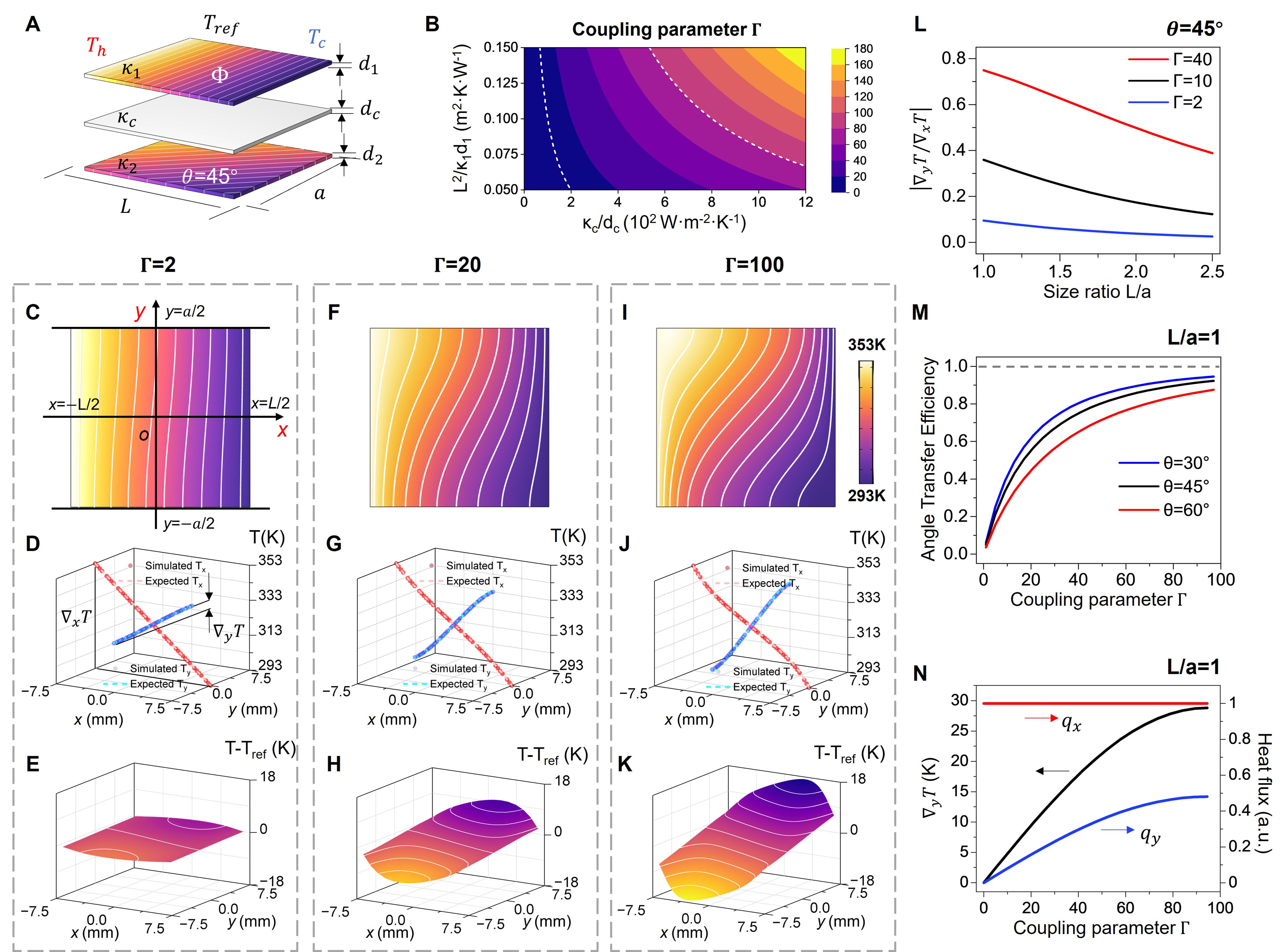
Figure 2. Thermal manipulation via interlayer coupling and corresponding simulation results. (A) Schematic illustration of the influence of bottom thermal field rotation by θ on the thermal reference value Tref of the upper layer; (B) The dimensionless coupling parameter Γ as a function of κc/dc and L2/κ1d1. The white dashed lines denote the contours at Γ = 10 and Γ = 80, delineating the boundaries between weak (Γ < 10), moderate (10 ≤ Γ ≤ 80), and strong (Γ > 80) coupling regimes; (C-K) Temperature distributions for three typical coupling strengths, all simulated with identical parameters: L = 15 mm, a = 15 mm, d1 = dc = d2 = 1 mm, θ = 45°, κ1 = 2.25 W/(m·K), κ2 =
Figure 2C-E illustrates the simulation results under the weak-coupling condition [κc = 0.02 W/(m·K), Γ = 2]. The upper-layer temperature contour [Figure 2C] shows nearly vertical isotherms, indicating that the thermal field is only weakly perturbed by the 45° lower-layer field. In good agreement with simulation and theoretical curves, the transverse and longitudinal temperature profiles along the center axes reveal a longitudinal temperature span close to the full 60 K applied bias, whereas the transverse difference ΔTy remains below 5% of ΔTx [Figure 2D]. The deviation field T - Tref exhibits a faint twist with peak deviations less than 2 K [Figure 2E]. In this regime, the coupling layer acts effectively as a thermal insulator, and heat transfer is dominated by one-dimensional longitudinal diffusion. Under moderate coupling [κc =
The central thermal deflection angle is maximized at an aspect ratio of unity (L/a = 1) and gradually declines as the aspect ratio increases further [Figure 2L], indicating that a square active area provides the most efficient geometric channel for transverse thermal transfer. Figure 2M shows that the thermal deflection transfer efficiency tanϕ/tanθ increases monotonically with Γ, converging toward unity at strong coupling. Saturation at large Γ arises because, once interlayer resistance becomes negligible, further increases in κc/dc yield diminishing returns in deflection angle; the upper-layer field cannot exceed the lower-layer driving field. Figure 2N demonstrates that the x-direction heat flux qx remains virtually invariant (varying by less than 1%) across all Γ, confirming that interlayer coupling acts primarily as a directional reallocating mechanism rather than a dissipative loss channel. Meanwhile, the y-direction temperature difference and the associated transverse heat flux qy rise monotonically with Γ. This amplified transverse thermal bias directly corresponds to an enhanced effective off-diagonal thermal conductivity κyx* in the upper layer. As derived in Supplementary Note 3, κyx*/κ1 = ΔTy/ΔTx, which scales linearly with the transverse-to-longitudinal temperature ratio. Supplementary Figure 7 further confirms that this linear scaling holds across the full angular range from -90° to +90°, including negative deflection angles, validating the all-azimuthal capability of the interlayer coupling mechanism. For Γ = 100, κyx* reaches approximately 60% of the intrinsic κ1, thereby establishing the thermodynamic link between interlayer thermal engineering and the emergent anisotropic transport that underpins the subsequent transverse thermoelectric response.
Experimental demonstration of interlayer thermal coupling
To experimentally validate the interlayer thermal coupling mechanism, anisotropic thermal conductive layers with engineered oblique thermal fields were fabricated. Notably, we measured the material properties of the experimental thermoelectric plate initially [Supplementary Figure 1], and corrected the simulated and designed model based on the actual characteristics. The key thermal conductivity adopts κ1 = 2.0 W/(m·K). Then, by engineering the off-diagonal thermal conductivity to satisfy tanθ = κxy/κyy, a uniform oblique thermal field is obtained; however, in a finite rectangular domain, this anisotropic conduction inevitably suffers from edge distortion[37]. To eliminate this boundary effect, we designed gradient-index boundary layers using coordinate transformation theory[38], constructing a virtual parallelogram space and extracting a central rectangular active area while mapping the lateral regions into impedance-matching transition zones [Supplementary Figure 8]. Crucially, the virtual spaces for all deflection angles share identical projected lengths along the x-direction, ensuring consistent heat flux densities regardless of the deflection angle [Supplementary Note 4]. The spatially varying thermal conductivity tensors in the transition regions are continuous and smooth [Supplementary Figure 9], and simulations confirm that the integrated boundary architecture successfully eliminates edge distortion throughout the central domain [Supplementary Figure 10].
To reconcile the continuous theoretical tensor with practical fabrication constraints, the boundary transition zones were discretized into piecewise-homogeneous elements via the finite-element midpoint method[35,39] [Supplementary Figure 11], where the Jacobian matrix is evaluated at the edge midpoints of each quadrilateral element to yield a uniform effective conductivity [Supplementary Note 5]. Supplementary Figures 12 and 13 present the calculated tensor component distributions under progressively refined mesh densities for both 30° and 60° configurations, and Supplementary Figure 14 demonstrates that the central active region consistently exhibits the target thermal gradient deflection regardless of mesh refinement, validating that the boundary layers function primarily as impedance-matching transition zones where moderate discretization is tolerated. Each discrete element was physically realized by laminated composites with tailored orientation angles and volume fractions [Supplementary Note 6]. We sequentially laminate the coupling and thermoelectric layers onto the thermal layer to fabricate the thermoelectric chip, then load predefined thermal boundaries to carry out interlayer thermal coupling tests [Figure 3A]. On the test bench, cured thermal conductive silicone gel fills the side areas next to the thermoelectric layer to complete boundary construction and guarantee intimate thermal contact. The corresponding effective thermal conductivity tensors are computed via transformation theory, enabling consistent thermal impedance matching throughout the whole device stack.
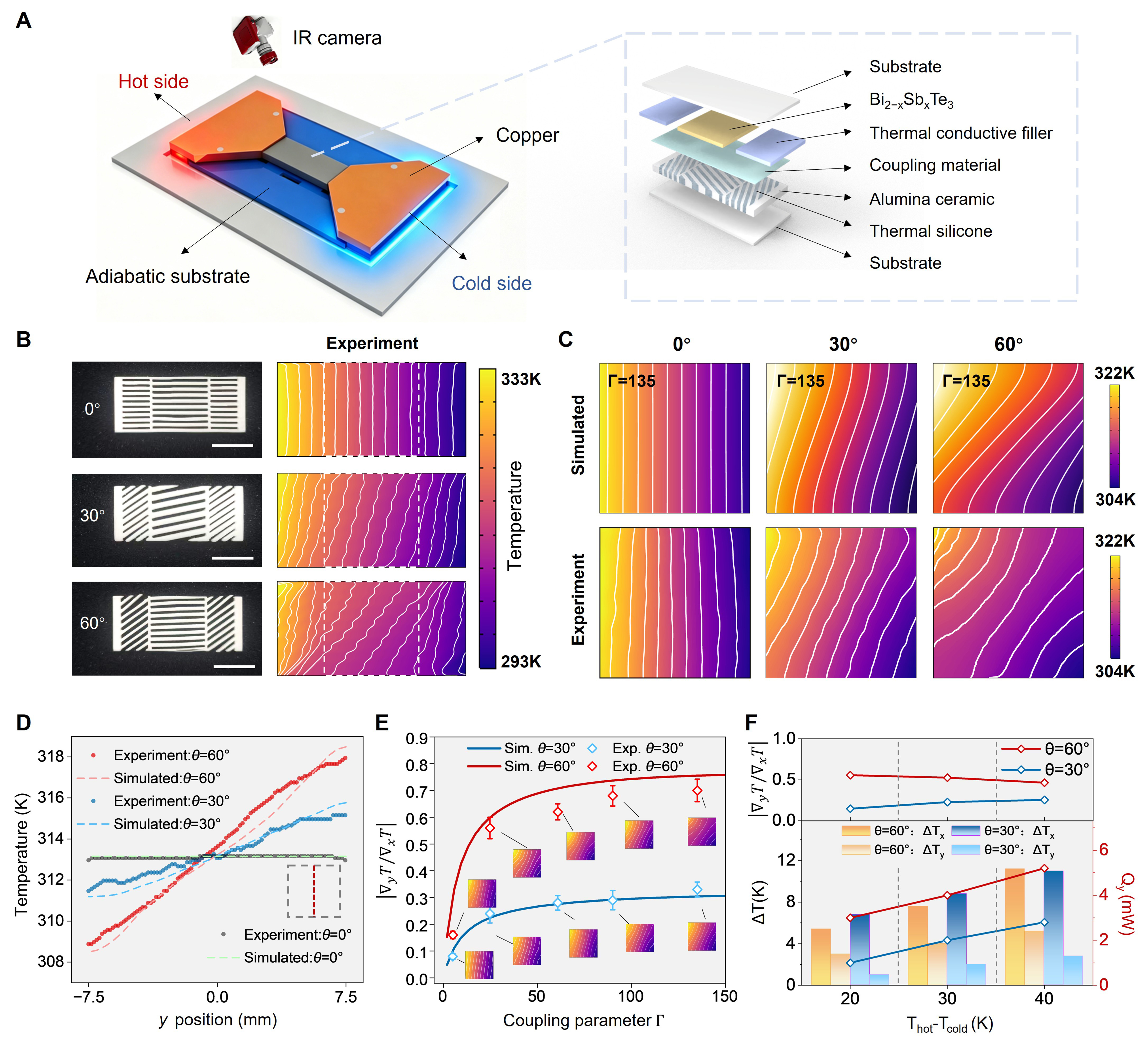
Figure 3. Experimental characterization of interlayer thermal coupling. (A) Schematic of the experimental setup. The inset presents an exploded-view illustration of the thermally coupled transverse TE chip; (B) Optical images of the thermal conductive layers with engineered deflection angles of 0°, 30°, and 60° (without thermal grease filling; scale bar, 10 mm) and the corresponding infrared thermal images showing the temperature fields; (C) Simulated (top) and experimental (bottom) temperature distributions of the thermoelectric layer at Γ = 135 for the three deflection angles (θ = 0°, 30°, and 60°); (D) Transverse temperature profiles along the y-axis of the upper layer for three different lower-layer deflection angles θ, comparing experimental data with simulation results. Red, blue, and black circles denote experimental data for θ = 60°, 30°, and 0°, respectively; dashed lines represent the corresponding simulated results; (E) The thermal deflection ratio |
Optical photographs of the fabricated thermal layers and the corresponding infrared thermal images are presented [Figure 3B]. Within the central 15 mm × 15 mm square area, the thermal layers with deflection angles successfully establish a uniform oblique thermal field consistent with the designed angle, featuring parallel isotherms of constant slope, whereas the 0° control sample maintains straight longitudinal isotherms. Near the edges, the isotherms smoothly transition from the oblique orientation in the bulk to a nearly vertical alignment at the outer boundaries, evidencing that the transformation-based boundary layers effectively suppress edge distortion and maintain the intended heat flux topology throughout the active region. We subsequently characterized interlayer coupling by placing the upper thermoelectric layer atop the substrates separated by a 0.25 mm PI coupling film [κc = 0.3 W/(m·K)], yielding Γ = 135 based on κ1 =
Figure 3D presents quantitative line scans along the central y-axis of the upper thermoelectric layer. The experimental transverse temperature profiles exhibit excellent agreement with simulation results across all three deflection angles (0°, 30°, and 60°), with a maximum deviation of less than 5% over the entire scanning range, thereby validating the predictive capability of the theoretical model. To systematically tune the dimensionless coupling parameter Γ across the full dynamic range, we selected a series of coupling media spanning a broad thermal conductance range (see Supplementary Table 2 for detailed parameters). Figure 3E plots the measured thermal deflection ratio |
Interlayer thermal coupling induced transverse thermoelectric response
To isolate the extrinsic transverse thermoelectric response from the intrinsic longitudinal Seebeck effect, thermoelectric chips with a four-electrode layout were fabricated[40,41] [Figure 4A]. Numerical simulations of the electric potential distribution reveal that, as the lower-layer thermal deflection increases from 0° to 60°, the equipotential lines in the upper thermoelectric layer rotate from a strictly longitudinal orientation to progressively oblique configurations, while the transverse electric field component evolves from a negligible value to a pronounced single-peak profile with increasing amplitude [Figure 4B].
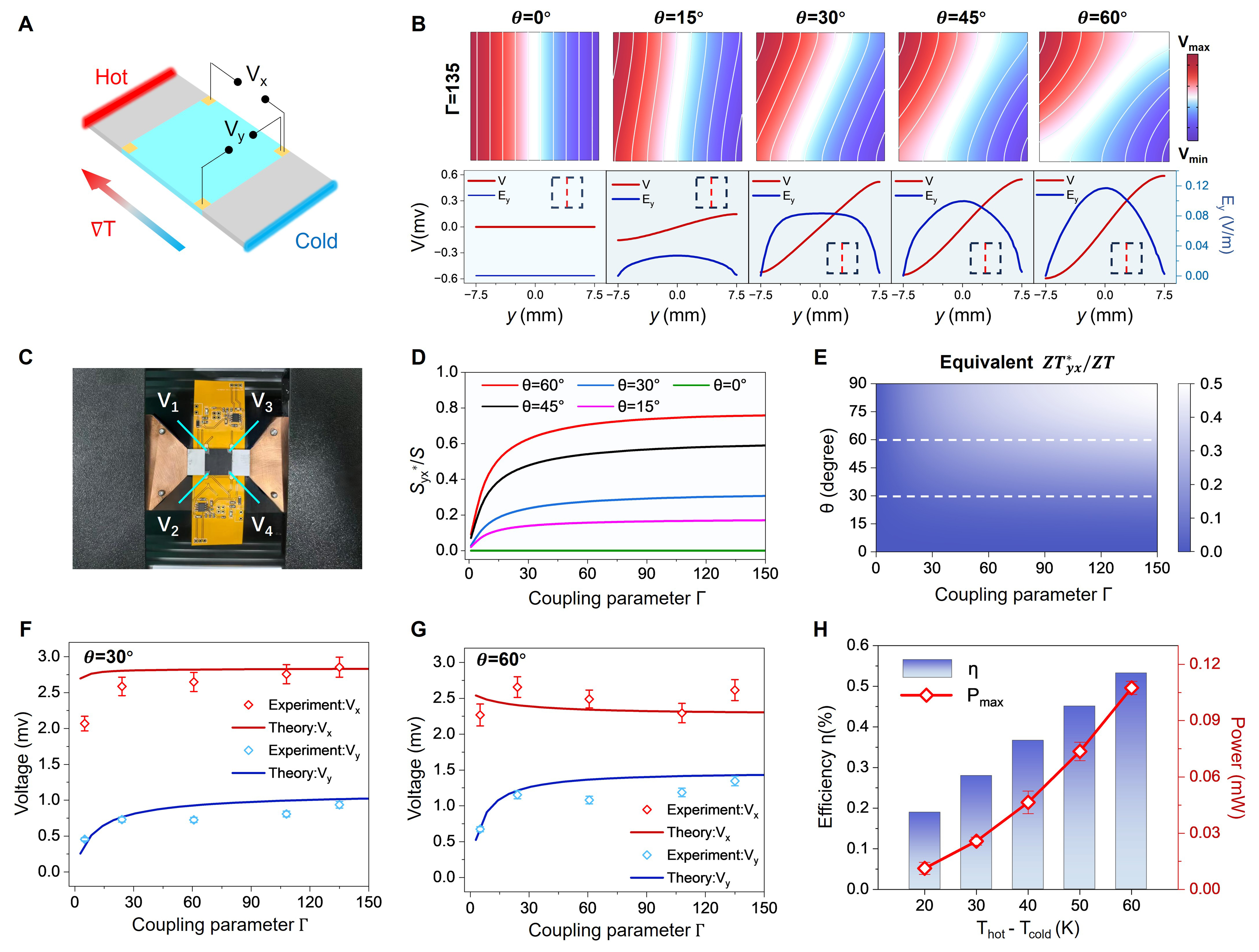
Figure 4. Transverse thermoelectric conversion driven by interlayer thermal coupling. (A) Schematic of the thermoelectric chip with four-probe electrode layout for oblique thermal coupling characterization; (B) Simulated electric potential contours (upper panels) and corresponding vertical-center-axis electric field profiles (lower panels). The red and blue lines denote the electric potential V and the transverse electric field Ey, respectively; (C) Optical photograph of the fabricated four-probe device mounted on the measurement stage; (D) Effective off-diagonal Seebeck coefficient induced by interlayer thermal coupling plotted against the coupling parameter Γ. The colored curves represent different lower-layer deflection angles: red: θ = 60°, black: θ = 45°, blue: θ = 30°, pink: θ = 15° and green: θ = 0°; (E) Calculated distribution of the transverse effective figure of merit ZTyx*/ZT. White dashed lines mark the representative deflection angles θ = 30° and θ = 60° adopted for experimental characterization; (F) Experimental open-circuit voltages and numerical predictions for longitudinal (Vx, red) and transverse (Vy, blue) configurations at θ = 30° under an applied temperature difference of 40 K. Error bars denote the SD of experimental replicates; (G) Corresponding experimental and theoretical voltages for θ = 60°; (H) Experimentally measured transverse thermoelectric conversion efficiency η (bar charts) and maximum output power Pmax (red line) as functions of the applied temperature difference. SD: Standard deviation.
The fabricated device mounted on the measurement stage is shown in Figure 4C. To eliminate the influence of contact and lead resistances, a two-pair shorting method was adopted: for the longitudinal measurement, electrodes V1 and V2 were shorted together to serve as one terminal while electrodes V3 and V4 were shorted to serve as the other, thereby probing the voltage drop along the x-direction; for the transverse measurement, electrodes V1 and V3 were shorted as one terminal and electrodes V2 and V4 as the other, capturing the voltage drop across the y-direction. This four-probe configuration ensures that the measured voltages reflect purely the thermoelectric potential generated by the oblique thermal field, free from spurious ohmic drops at the interfaces. The effective off-diagonal Seebeck coefficient Syx* induced by interlayer thermal coupling increases monotonically with the coupling parameter Γ and eventually saturates at strong coupling, consistent with the theoretical prediction in Equation (4) [Figure 4D]. The physical origin of this saturation lies in the asymptotic behavior of the transverse-to-longitudinal temperature ratio ΔTy/ΔTx. Furthermore, varying the coupling-layer thickness of silica aerogel and PDMS films at θ = 60° yields a monotonic decrease in Syx*/S with increasing thickness [Supplementary Figure 18], consistent with Γ
Experimental open-circuit voltages for longitudinal and transverse configurations at lower-layer deflection angles of 30° and 60° under an applied temperature difference of 40 K are presented [Figure 4F and G]; complementary data for 15° and 45° are provided in Supplementary Figure 19. The longitudinal voltage remains nearly constant across all deflection angles, as it is governed primarily by the applied longitudinal thermal bias ΔTx. In contrast, the transverse voltage rises substantially from approximately 0.2 to 1.0 mV at 30°, and from approximately 0.5 to 1.5 mV at 60°. The monotonic growth of the transverse voltage with θ directly validates that the transverse thermoelectric response is extrinsically engineered by the interlayer thermal coupling rather than by any intrinsic material anisotropy. The experimentally measured transverse thermoelectric conversion efficiency η and the maximum output power Pmax under different applied temperature gradients are summarized in Figure 4H. Bar-chart data for additional deflection angles are provided in Supplementary Figure 20. Under the 60°, Γ = 135 configuration, the conversion efficiency increases monotonically from 0.19% at ΔT = 20 K to 0.53% at ΔT = 60 K, while the maximum transverse output power grows from 0.011 to 0.107 mW over the same span. The modest efficiencies stem from parasitic dissipation at interlayer interfaces and boundary transition zones, which attenuates the central thermal gradient and causes the experimentally determined conversion efficiency to fall below the standard thermoelectric efficiency relation under identical boundary conditions. Systematic analysis of the normalized off-diagonal Seebeck coefficient across the full parameter space reveals that interfacial contact thermal resistance constitutes the dominant baseline loss, while boundary-layer fabrication tolerances become increasingly pronounced at larger deflection angles [Supplementary Note 8 and Supplementary Figure 21]. Finite-element simulations incorporating interfacial contact thermal resistance Rs reveal that both the transverse power factor and output power density decrease monotonically with increasing Rs [Supplementary Figure 17E and F], confirming that interfacial thermal resistance is the primary performance bottleneck. To verify that this bottleneck is not specific to the choice of thermoelectric material, complementary simulations were performed using PbTe as the upper layer. The resulting normalized off-diagonal Seebeck coefficient Syx*/S falls precisely onto the theoretical curve derived from the Bi2Te3-based model [Supplementary Figure 22], demonstrating that the transverse response is governed solely by interlayer thermal coupling geometry rather than by intrinsic material properties. Consequently, performance gains can be achieved by optimizing interlayer impedance matching and minimizing parasitic leakage through refined coupling-layer engineering, without relying on exotic material selection.
Conformal thermoelectric device for non-planar surfaces
Rigid thermoelectric modules inherently struggle to establish conformal thermal contact on curved surfaces, leaving substantial heat-harvesting opportunities untapped on non-planar geometries such as human skin, wearable electronics, and cylindrical industrial piping. The present bilayer design overcomes this limitation by physically separating thermal field engineering and thermoelectric conversion into independently optimizable layers, allowing each layer to be thinned, patterned, and made flexible without compromising the interlayer coupling mechanism. To extend the interlayer-coupled architecture beyond planar geometries, the assembled thermoelectric chip was integrated onto an FPC board to form a mechanically compliant conformal device[42,43]. The FPC substrate, pre-patterned with copper traces and contact pads, enabled seamless integration of the Bi2Te3 thermoelectric layer, the coupling film, and the tilted thermal conductive layer into a single stack. A preamplifier circuit was co-mounted on the same FPC board to minimize lead length and electromagnetic interference. The total thickness of the flexible bilayer device was approximately 2.5 mm, and the bending stiffness was dominated by the thin PI substrate rather than the rigid ceramic components, ensuring that the stack remained mechanically compliant [Figure 5A]. Conformal attachment was demonstrated by mounting the device onto a cylindrical surface (radius of curvature, 50 mm) and by wearing it directly on a human arm [Figure 5B]. The flexible stack readily conformed to the curved geometry without delamination or cracking of the thermoelectric layer, confirming that the mechanical compliance was preserved after integration.
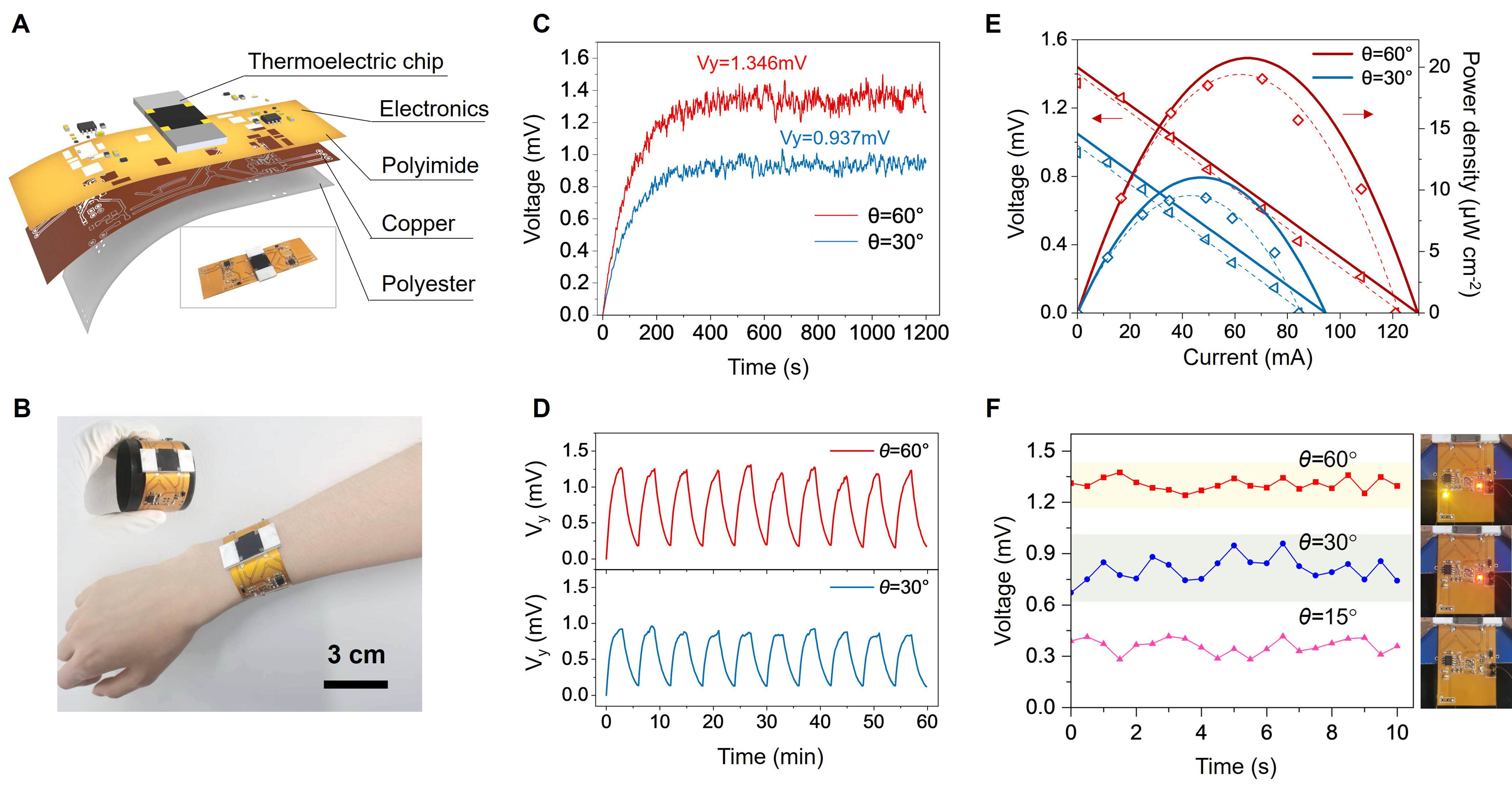
Figure 5. Conformal attachment and energy harvesting on curved surfaces. (A) Schematic illustration of the flexible device integrated on an FPC substrate. Inset: optical photograph; (B) Optical photograph of the conformally attached device on a cylindrical surface and worn on a human arm (scale bar, 3 cm). The photograph of the device worn on the human arm was taken with the informed consent of the volunteer; (C) Time-dependent transverse open-circuit voltage (Vy) measured at a fixed temperature difference of ΔT = 40 K. The red and blue curves correspond to θ = 60° and θ = 30°, respectively; (D) Thermal cycling stability of the conformal devices. Transverse open-circuit voltage (Vy) of the θ = 30° (blue) and θ = 60° (red) flexible devices recorded over 60 min under periodic thermal cycling at ΔT = 40 K; (E) Current–voltage characteristics and corresponding power densities (normalized to the 15 mm × 15 mm active area) for the 60° and 30° flexible devices. Red and blue colors correspond to θ = 60° and θ = 30°, respectively. Solid lines and scattered points denote simulation and experimental results, respectively, while dashed lines correspond to fitted curves; (F) Proof-of-concept demonstration of an angle-resolved heat-flux indicator. (Left) Time-dependent transverse output voltage of the device under a fixed thermal bias (ΔT = 40 K) for θ = 60° (red), 30° (blue), and 15° (pink), driving a dual-LED threshold circuit. (Right) Corresponding optical states of the indicator: dual-LED ON (top), red-LED ON (middle), and dual-LED OFF (bottom). FPC: Flexible printed circuit.
Two sets of flexible devices with lower-layer deflection angles of 30° and 60° were characterized. A uniform temperature difference of ΔT = 40 K was applied using the same PTC heater and Peltier cooler configuration. The transverse open-circuit voltage Vy was recorded continuously over a 1,200-second interval. As shown in Figure 5C, the voltage stabilized within 360 s at approximately 0.937 and 1.346 mV for the 30° and 60° configurations, respectively, with SDs below 0.08 and 0.12 mV. Thermal cycling over 60 min yields reproducible periodic output without obvious degradation [Figure 5D], confirming robust interlayer coupling under cyclic thermal loads. To address mechanical durability, bending-cycle tests were conducted at a fixed radius of 50 mm and static bending tests were performed at various radii down to 20 mm [Supplementary Figure 23]. Cross-sectional micrographs confirm intact layer interfaces without delamination after 150 bending cycles [Supplementary Figure 24]. The output current–voltage characteristics and corresponding power densities normalized to the 15 mm × 15 mm active area of the thermoelectric chip are presented in Figure 5E; solid lines and scattered points denote simulation and experimental results, respectively, while dashed lines correspond to fitted curves. Although the measured power densities fall approximately 10% below theoretical predictions owing to additional contact thermal resistance at the curved interface and lateral heat leakage through the PI substrate, the 60° device consistently outperforms the 30° counterpart, confirming that the interlayer thermal coupling mechanism remains effective in the flexible, non-planar geometry.
A side-by-side comparison with representative transverse thermoelectric strategies [Supplementary Table 3] highlights that the present architecture offers full-range angular tunability and conformal adaptability without requiring cryogenic temperatures or external magnetic fields, distinguishing it from topology-driven and magneto-thermoelectric alternatives. Furthermore, by integrating an amplification stage and a dual-LED threshold indicator onto the FPC substrate, the device directly converts heat-flux deflection angle into discrete optical states [Figure 5F]. Under a fixed thermal bias of ΔT = 40 K, the three configurations (θ = 60°, 30°, and 15°) yield distinct outputs: dual-LED ON above ~1.0 mV, red-LED ON above ~0.65 mV, and dual-LED OFF below the threshold, respectively. This proof-of-concept validates that the geometrically induced transverse voltage can directly drive low-threshold microelectronics, establishing a feasible route toward conformal, angle-resolved thermal sensors.
Limitations and outlook
This study demonstrates that interlayer thermal coupling can decouple thermal field engineering from thermoelectric conversion, enabling a continuously tunable transverse response in intrinsically isotropic materials. While the predictive capability of the dimensionless coupling parameter Γ has been validated across the full dynamic range, three principal limitations should be acknowledged. First, interfacial contact thermal resistance and fabrication tolerances of the thermal conductive layer cause the experimentally measured transverse thermoelectric performance to fall below ideal theoretical predictions, particularly at large deflection angles. Second, the present devices were demonstrated at preset, discrete deflection angles and coupling strengths; in-situ tunability of the thermal field within a single device remains to be experimentally demonstrated. Third, the current work is restricted to a single-chip architecture; scaling to large-area, multi-module conformal arrays remains an open engineering challenge.
Looking forward, several directions merit exploration. The integration of actively tunable thermal interfaces - such as thermally responsive polymers or pressure-adjustable coupling layers - offers a pathway to liberate the architecture from static film-based configurations[44-47], enabling dynamic modulation of the transverse output without physical replacement of the coupling medium. For the thermal metamaterial layer, the prescribed anisotropic conductivity can be realized in monolithic thin films via scalable processing routes such as blade coating or roll-to-roll assembly of aligned two-dimensional nanofillers in polymer matrices, liberating the design from discrete lamination[48,49]. Beyond wearable electronics, the conformal nature of the device architecture suggests immediate applicability to curved industrial surfaces: conformally wrapping the bilayer stack around exhaust pipes or cylindrical heat exchangers opens the possibility of harvesting otherwise dissipated thermal energy from non-planar geometries where conventional flat modules fail to make adequate thermal contact[50,51]. Extension to organic and thin-film thermoelectric systems would further reduce weight and bending stiffness[52], broadening the design space toward epidermal patches and soft implantable energy harvesters. Ultimately, tiling the architecture into distributed multi-module arrays with integrated energy management circuits establishes a scalable route toward large-area, shape-adaptive thermoelectric harvesting on arbitrarily curved surfaces, translating the present proof-of-concept into deployable soft energy systems[53,54].
CONCLUSIONS
We have demonstrated a bilayer thermoelectric architecture that induces an effective, planar, transverse thermoelectric response in an intrinsically isotropic material through interlayer thermal coupling. By physically separating thermal field engineering from thermoelectric conversion into distinct layers, the design eliminates the co-planar impedance inherent in conventional coupled-field structures, breaks the constraint of cascading configurations, and decouples thermal transport geometry from electrical conversion into independently optimizable degrees of freedom. A dimensionless coupling parameter provides a predictive framework for all-azimuthal oblique thermal field control, experimentally validated through infrared thermography and four-probe electrode measurements. Integration onto a flexible substrate demonstrates a conformal harvesting architecture that enriches the design paradigms and integration modes of thermoelectric devices. This work establishes a field-coupling-dependent transverse thermoelectric strategy that opens a route towards material-agnostic control of heat and charge.
DECLARATIONS
Authors’ contributions
Conceptualization: Ding, S.; Ge, C.; Xu, Z.
Methodology: Ding, S.; Ge, C.; Xu, Z.; Sui, J.; Ma, H.; Wang, H.; Li, T.
Formal analysis: Ding, S.; Ge, C.
Funding acquisition, supervision: Li, T.
Writing - original draft: Ding, S.; Ge, C.
Writing - review and editing: Li, Y.; Wang, L.; Zhu, Y.; Xu, Z.
All authors have read the manuscript and approved the final version.
Availability of data and materials
The authors declare that the primary data supporting the findings of this study are available within the paper and its Supplementary Materials. Additional data are available from the corresponding authors upon reasonable request.
AI and AI-assisted tools statement
During the preparation of this manuscript, the authors used the AI tool ChatGPT (GPT-5.5, released 2026-04-23) to assist with English language editing, grammatical correction, and improving the clarity and readability of the text. These tools were not used to generate scholarly arguments, develop the conceptual framework, or draw the conclusions of the article. All AI-assisted outputs were carefully reviewed, edited, and verified by the authors, who take full responsibility for the accuracy, originality, and integrity of the final manuscript.
Financial support and sponsorship
This work was supported by National Key Research and Development Program of China (Grant No. 2023YFB4604100), the National Natural Science Foundation of China (Grants No. 52322502, 52602005, T2550093), the Zhejiang Provincial Natural Science Foundation (Grant No. LR26A050001), the Pre-research Task of State Key Laboratory of Robotics and Systems (HIT), Fundamental Research Funds for Central Universities, and the State Key Laboratory of Luminescence Science and Technology (CIOMP), E60652A2M1.
Conflicts of interest
All authors declared that there are no conflicts of interest.
Ethical approval and consent to participate
This study only involved non-invasive photographic documentation of the device worn on a human arm and did not involve any invasive procedures, human health risks, or clinical interventions. According to the Measures for the Ethical Review of Life Sciences and Medical Research Involving Humans (Guo Wei Ke Jiao Fa [2023] No. 4), formal ethical approval was not required. Written informed consent was obtained from the volunteer.
Consent for publication
Not applicable.
Copyright
© The Author(s) 2026.
Supplementary Materials
REFERENCES
2. Bell, L. E. Cooling, heating, generating power, and recovering waste heat with thermoelectric systems. Science 2008, 321, 1457-61.
3. Zhao, L.; Dravid, V. P.; Kanatzidis, M. G. The panoscopic approach to high performance thermoelectrics. Energy. Environ. Sci. 2014, 7, 251-68.
4. Aljaghtham, M.; Celik, E. Design of cascade thermoelectric generation systems with improved thermal reliability. Energy 2022, 243, 123032.
5. He, J.; Li, K.; Jia, L.; Zhu, Y.; Zhang, H.; Linghu, J. Advances in the applications of thermoelectric generators. Appl. Therm. Eng. 2024, 236, 121813.
6. Hu, H.; Han, S.; Yang, Y.; et al. Observation of topological edge states in thermal diffusion. Adv. Mater. 2022, 34, e2202257.
7. Jin, P.; Liu, J.; Xu, L.; et al. Tunable liquid-solid hybrid thermal metamaterials with a topology transition. Proc. Natl. Acad. Sci. U. S. A. 2023, 120, e2217068120.
8. Xu, L.; Liu, J.; Xu, G.; Huang, J.; Qiu, C. W. Giant, magnet-free, and room-temperature Hall-like heat transfer. Proc. Natl. Acad. Sci. U. S. A. 2023, 120, e2305755120.
9. Zhou, W.; Sasaki, T.; Uchida, K. I.; Sakuraba, Y. Direct-contact Seebeck-driven transverse magneto-thermoelectric generation in magnetic/thermoelectric bilayers. Adv. Sci. 2024, 11, e2308543.
10. Zhou, Y.; Ding, T.; Xu, G.; et al. Sustainable heat harvesting via thermal nonlinearity. Nat. Rev. Phys. 2024, 6, 769-83.
11. Sakai, A.; Minami, S.; Koretsune, T.; et al. Iron-based binary ferromagnets for transverse thermoelectric conversion. Nature 2020, 581, 53-7.
12. Manako, H.; Ohsumi, S.; Sato, Y. J.; Okazaki, R.; Aoki, D. Large transverse thermoelectric effect induced by the mixed-dimensionality of Fermi surfaces. Nat. Commun. 2024, 15, 3907.
13. Chen, M.; Wang, J.; Liu, K.; et al. Topological Heusler magnets‐driven high‐performance transverse Nernst thermoelectric generators. Adv. Energy. Mater. 2024, 14, 2400411.
14. Uchida, K.; Hirai, T.; Ando, F.; Sepehri‐Amin, H. Hybrid transverse magneto‐thermoelectric cooling in artificially tilted multilayers. Adv. Energy. Mater. 2024, 14, 2302375.
15. Ando, F.; Hirai, T.; Adachi, H.; Uchida, K. Adiabatic transverse thermoelectric conversion enhanced by heat current manipulation in artificially tilted multilayers. Phys. Rev. Appl. 2025, 23, 064061.
16. Zhu, W.; Guo, X.; Sang, X.; et al. Fabrication and performance prediction of Ni/Bi0.5Sb1.5Te3 artificially-tilted multilayer devices with transverse thermoelectric effect. J. Power. Sources. 2021, 512, 230471.
17. Pan, Y.; He, B.; Feng, X.; et al. A magneto-thermoelectric with a high figure of merit in topological insulator Bi88Sb12. Nat. Mater. 2025, 24, 76-82.
18. Hu, H.; Feng, X.; Pan, Y.; et al. Multipocket synergy towards high thermoelectric performance in topological semimetal TaAs2. Nat. Commun. 2025, 16, 119.
19. Yang, F.; Zhang, Z.; Xu, L.; et al. Controlling mass and energy diffusion with metamaterials. Rev. Mod. Phys. 2024, 96, 015002.
21. Wang, Z.; Chen, J.; Ren, J. Geometric heat pump and no-go restrictions of nonreciprocity in modulated thermal diffusion. Phys. Rev. E. 2022, 106, L032102.
22. Yang, S.; Wang, J.; Dai, G.; Yang, F.; Huang, J. Controlling macroscopic heat transfer with thermal metamaterials: theory, experiment and application. Phys. Rep. 2021, 908, 1-65.
23. Chen, M.; Zhang, J.; Shen, X.; Zhu, G.; Li, B. Metamaterials based on solid composites enable continuous and tunable thermal conductivity anisotropy for thermal management applications. Device 2024, 2, 100500.
24. Zhang, Y.; Jiang, W. Z.; Pan, Y.; et al. Temperature-responsive metamaterials made of highly sensitive thermostat metal strips. Sci. Adv. 2024, 10, eads0892.
25. Xu, Z.; Xie, F.; Li, J.; et al. Thermoelectric metadevice-assisted cooperative magnetic-free transverse energy transport. Cell. Rep. Phys. Sci. 2024, 5, 102251.
26. Li, Y.; Xu, L.; Qiu, C. W. Thermal metamaterials: controlling the flow of heat. World Scientific Publishing Co. Pte. Ltd.; 2025.
27. Luo, D.; Wang, R.; Yu, W.; Zhou, W. A novel optimization method for thermoelectric module used in waste heat recovery. Energy. Convers. Manag. 2020, 209, 112645.
28. Jin, P.; Xu, L.; Xu, G.; Li, J.; Qiu, C. W.; Huang, J. Deep learning-assisted active metamaterials with heat-enhanced thermal transport. Adv. Mater. 2024, 36, e2305791.
30. Snyder, G. J.; Ursell, T. S. Thermoelectric efficiency and compatibility. Phys. Rev. Lett. 2003, 91, 148301.
31. Kim, H.; Gibbs, Z. M.; Tang, Y.; Wang, H.; Snyder, G. J. Characterization of Lorenz number with Seebeck coefficient measurement. APL. Mater. 2015, 3, 041506.
32. Fan, C.; Wu, C.; Wang, Y.; Wang, B.; Wang, J. Thermal metamaterials: from static to dynamic heat manipulation. Phys. Rep. 2024, 1077, 1-111.
33. Vaziri, S.; Yalon, E.; Muñoz Rojo, M.; et al. Ultrahigh thermal isolation across heterogeneously layered two-dimensional materials. Sci. Adv. 2019, 5, eaax1325.
34. Zhu, Z.; Wang, Z.; Liu, T.; et al. Arbitrary-shape transformation multiphysics cloak by topology optimization. Int. J. Heat. Mass. Transf. 2024, 222, 125205.
35. Yang, F.; Xu, L.; Wang, J.; Huang, J. Transformation theory for spatiotemporal metamaterials. Phys. Rev. Appl. 2022, 18, 034080.
36. Uchida, K.; Heremans, J. P. Thermoelectrics: from longitudinal to transverse. Joule 2022, 6, 2240-5.
37. Ma, Y.; Liu, Y.; Raza, M.; Wang, Y.; He, S. Experimental demonstration of a multiphysics cloak: manipulating heat flux and electric current simultaneously. Phys. Rev. Lett. 2014, 113, 205501.
38. Xu, L.; Dai, G.; Yang, F.; et al. Free-form and multi-physical metamaterials with forward conformality-assisted tracing. Nat. Comput. Sci. 2024, 4, 532-41.
39. Liu, Y.; Cao, X.; Li, J.; et al. Dual-functional thermal metamaterials: decoupling heat flux and temperature fields for advanced thermal management. Small. Methods. 2026, 10, e2500469.
40. Zheng, Z.; Shi, X.; Ao, D.; et al. Harvesting waste heat with flexible Bi2Te3 thermoelectric thin film. Nat. Sustain. 2023, 6, 180-91.
41. Liu, Y.; Zhang, Q.; Huang, A.; et al. Fully inkjet-printed Ag2Se flexible thermoelectric devices for sustainable power generation. Nat. Commun. 2024, 15, 2141.
42. Zhang, X.; Hou, Y.; Yang, Y.; et al. Stamp-like energy harvester and programmable information encrypted display based on fully printable thermoelectric devices. Adv. Mater. 2023, 35, e2207723.
43. Gautam, R.; Hirai, T.; Alasli, A.; et al. Creation of flexible spin-caloritronic material with giant transverse thermoelectric conversion by nanostructure engineering. Nat. Commun. 2024, 15, 2184.
44. Li, C.; Ma, Y.; Tian, Z. Thermal switching of thermoresponsive polymer aqueous solutions. ACS. Macro. Lett. 2018, 7, 53-8.
46. Windberger, M. S.; Dimitriou, E.; Rendl, S.; Wewerka, K.; Wiesbrock, F. Temperature-triggered/switchable thermal conductivity of epoxy resins. Polymers 2020, 13, 65.
47. Tan, H.; Zhao, Y.; Jin, P.; et al. Bioinspired energy-free temperature gradient regulator for significant enhancement of thermoelectric conversion efficiency. Proc. Natl. Acad. Sci. U. S. A. 2025, 122, e2424421122.
48. Zhai, Y.; Ma, Y.; David, S. N.; et al. Scalable-manufactured randomized glass-polymer hybrid metamaterial for daytime radiative cooling. Science 2017, 355, 1062-6.
49. Li, L.; Cheng, Q. Anisotropic thermally conductive films based on two‐dimensional nanomaterials. Interdiscip. Mater. 2024, 3, 847-64.
50. Zadan, M.; Wertz, A.; Shah, D.; et al. Stretchable thermoelectric generators for self‐powered wearable health monitoring. Adv. Funct. Mater. 2024, 34, 2404861.
51. Zhang, D.; Sia, S. A.; Solco, S. F. D.; Xu, J.; Suwardi, A. Energy harvesting through thermoelectrics: topological designs and materials jetting technology. Soft. Sci. 2023, 3, 1.
52. Yang, D.; Shi, X. L.; Li, M.; et al. Flexible power generators by Ag2Se thin films with record-high thermoelectric performance. Nat. Commun. 2024, 15, 923.
53. Yang, Q.; Yang, S.; Qiu, P.; et al. Flexible thermoelectrics based on ductile semiconductors. Science 2022, 377, 854-8.
Cite This Article
 Open Access
How to Cite
Download Citation
Export Citation File:
Type of Import
Tips on Downloading Citation
Citation Manager File Format
Type of Import
Direct Import: When the Direct Import option is selected (the default state), a dialogue box will give you the option to Save or Open the downloaded citation data. Choosing Open will either launch your citation manager or give you a choice of applications with which to use the metadata. The Save option saves the file locally for later use.
Indirect Import: When the Indirect Import option is selected, the metadata is displayed and may be copied and pasted as needed.
About This Article
Special Topic
Copyright

Data & Comments
Data
0








Comments
Comments must be written in English. Spam, offensive content, impersonation, and private information will not be permitted. If any comment is reported and identified as inappropriate content by OAE staff, the comment will be removed without notice. If you have any queries or need any help, please contact us at support@oaepublish.com.