
fig6
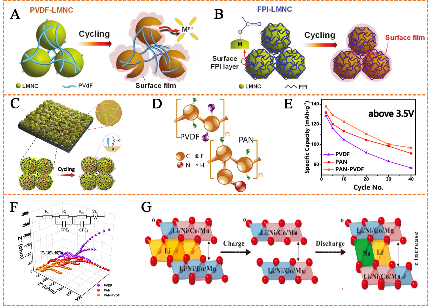
Figure 6. (A) Schematic illustration of PVDF-LMNC and (B) FPI-LMNC cathode before and after 100 cycles; (A and B) are reprinted with permission from Ref.[4], Copyright © 2017, Wiley; (C) Sketch map of XG cathodes; (C) is reprinted with permission from Ref.[47], Copyright © 2019, Elsevier; (D) Sketch map of PAN and PVDF; (D-F) are reprinted with permission from Ref.[41], Copyright © 2017, Elsevier; (E) Divided capacity of PAN-PVDF, PAN and PVDF cathodes above 3.5 V; (F) Nyquist plots of different electrodes in 1st, 10th, 40th at the state of DOD ≈ 50%; (G) Schematic diagram of ion-exchange process provided by CMC during cycling. (G) is reprinted with permission from Ref.[72], Copyright © 2016, Wiley. PVDF: Poly(vinylidene fluoride); LMNC: Li1.13Mn0.463Ni0.203Co0.203O2; FPI: fluorinated polyimide; PAN: polyacrylonitrile; XG: xanthan gum; DOD: depth of discharge: CMC: carboxymethyl cellulose.