

fig1
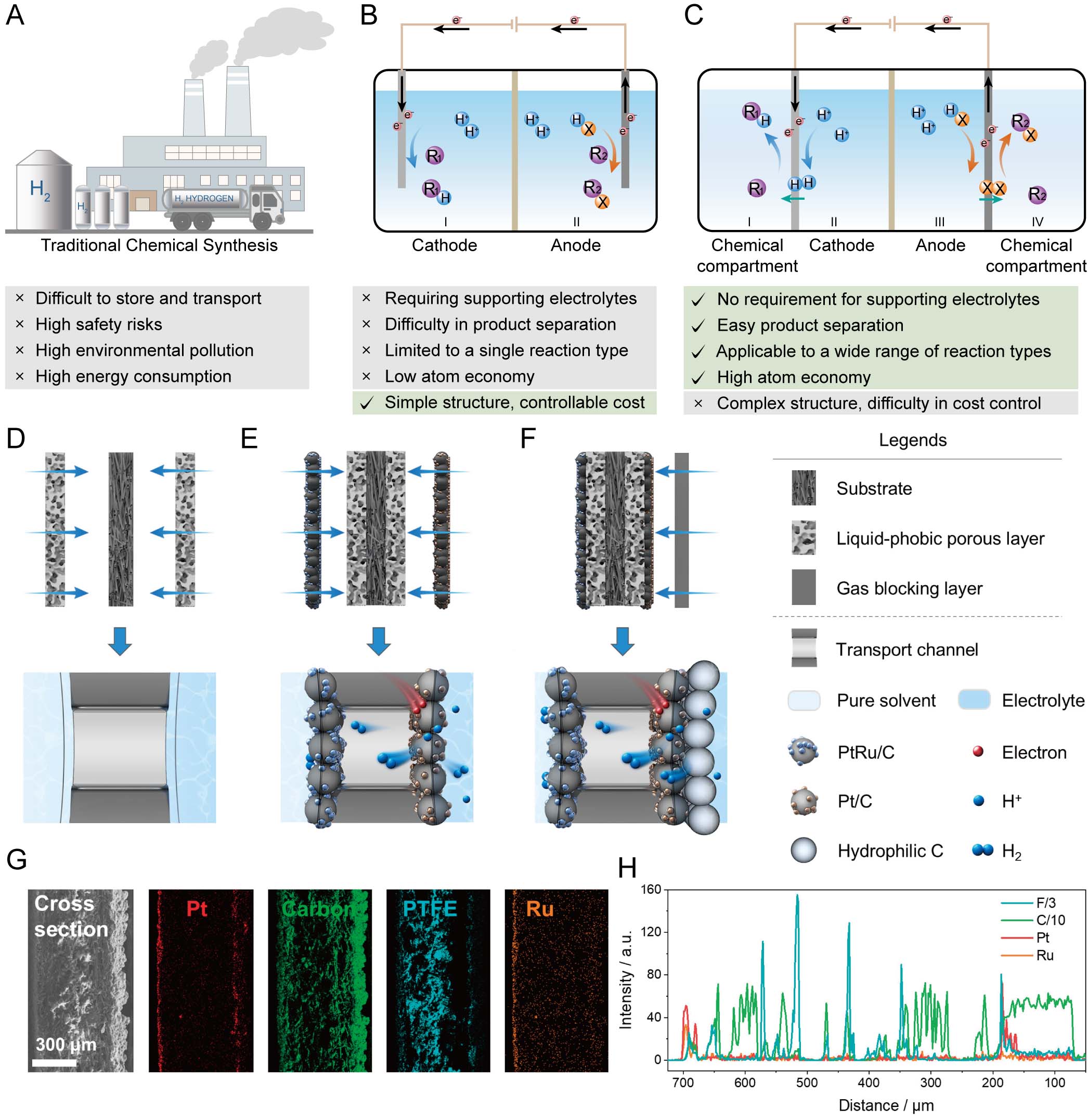
Figure 1. (A) Conceptual diagram of the drawbacks of traditional chemical hydrogenation synthesis. (B) Traditional electrochemical reactor. (C) Four-chamber electrochemical reactor for electrosynthesis without an auxiliary electrolyte. (D) Liquid-phobic interface structure. (E) Catalytic layer structure. (F) Gas barrier layer structure. (G) Cross-sectional SEM image of the membrane used for CYC-ol electrosynthesis and corresponding elemental distribution map and (H) Elemental distribution spectrum[4]. (D-H) is reproduced from[4], under the terms of the CC BY-NC-ND license, without modification.