



fig5
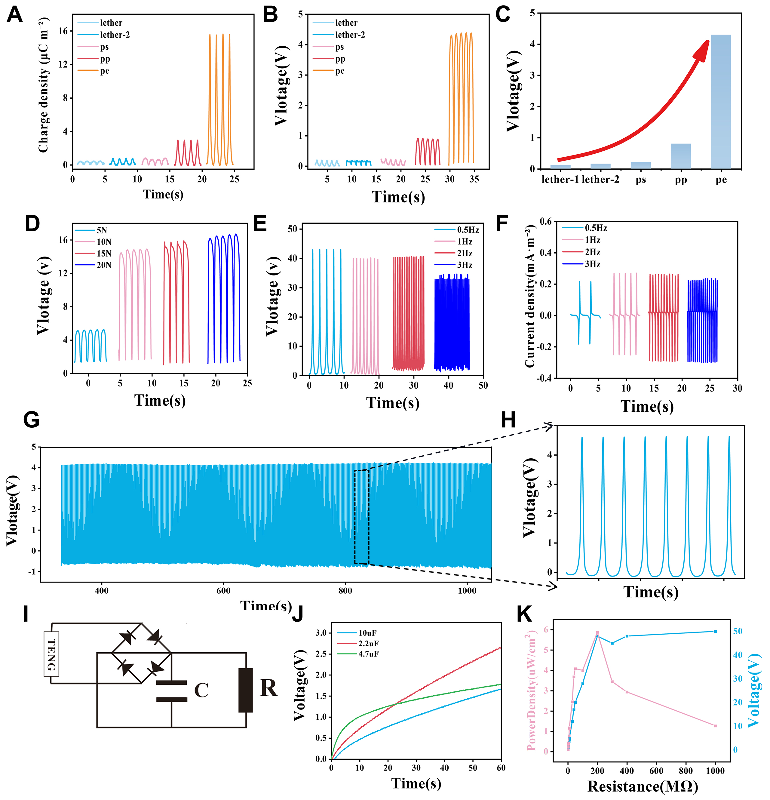
Figure 5. Comprehensive triboelectric performance, parameter dependence, long-term durability, and energy-harvesting applications of the PVA/MXene film. (A-C) Output voltage and transferred charge profiles when the composite film is paired with various distinct contact objects (leather 1, leather 2, PS, PP, and PE). (D) Output voltage variations under different mechanical contact forces ranging from 5 to 20 N (1 Hz). (E and F) Dependence of the output voltage and short-circuit current on the operating frequency. (G and H) Long-term durability and continuous cycling stability tests over 1,000 contact-separation cycles (5 N, 1 Hz), demonstrating the mechanical and electrical robustness of the device. (I) Schematic circuit diagram of the energy-harvesting system integrated with a full-wave rectifier bridge. (J) Voltage-time charging curves for different commercial capacitors (2.2, 4.7, and 10 μF; rated voltage, 10 V) driven by the self-powered system. (K) Output voltage and calculated power density (normalized to the effective contact area of ≈2 cm2) plotted as a function of external load resistance to evaluate impedance matching; the peak output voltage of 50 V was obtained at 25 N and 1 Hz with the Ecoflex counter layer Comprehensive triboelectric performance, parameter dependence, long-term durability, and energy-harvesting applications of the PVA/MXene film. (A-C) Output voltage and transferred charge profiles when the composite film is paired with various distinct contact objects. (D) Output voltage variations under different mechanical contact forces ranging from 5 to 20 N. (E and F) Dependence of the output voltage and Short-circuit current on alternative operating frequencies. (G and H) Long-term durability and continuous cycling stability tests demonstrating the mechanical and electrical robustness of the device. (I) Schematic circuit diagram of the energy-harvesting system integrated with a full-wave rectifier bridge. (J) Voltage-time charging curves for different commercial capacitors (2.2, 4.7, and 10 μF) driven by the self-powered system. (K) Output voltage and calculated power density plotted as a function of external load resistance to evaluate impedance matching.