


fig5
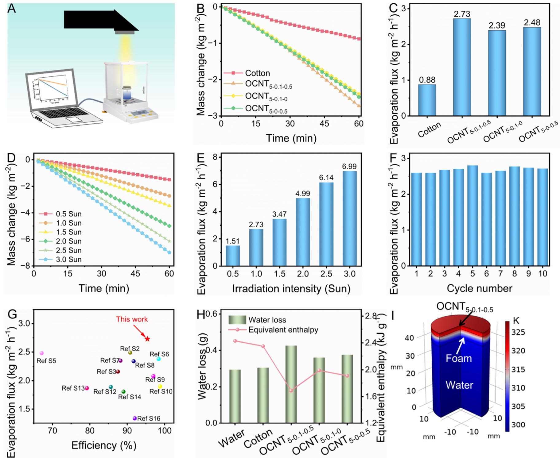
Figure 5. (A) Schematic diagram of interfacial solar steam generation. (B) Water mass losses of evaporation systems and (C) evaporation fluxes for various evaporators under 1 Sun irradiation. (D) Water mass change and (E) evaporation flux of the OCNT5-0.1-0.5 evaporator under solar intensities ranging from 0.5 to 3 Sun. (F) Water evaporation fluxes of the OCNT5-0.1-0.5 evaporator over 10 cycles. (G) Solar-evaporation performance comparison between the OCNT5-0.1-0.5 evaporator and previously reported evaporators. (H) Mass loss of water in the dark and vaporization enthalpy for various evaporators. (I) COMSOL simulation of the temperature distribution in the OCNT5-0.1-0.5 evaporation system.