



Hierarchical porous scaling-up TENGs with enhanced charge density via conductive-ferroelectric hybrid fillers for intelligent home ecosystems
 0
Abstract
In recent years, the application scope of triboelectric nanogenerators (TENGs) has expanded from portable electronic devices to large-scale energy harvesting and intelligent home ecosystems. However, as the size of TENGs increases, traditional thin-film materials become more susceptible to air breakdown and dielectric breakdown, which hampers further enhancement of charge density and output stability. In this study, reduced graphene oxide (rGO)-Fe and BaTiO3 (BT) particles were incorporated as conductive-ferroelectric hybrid fillers into an Ecoflex matrix to construct a hierarchical porous composite sponge-based TENG. The charge-capturing capability of the triboelectric interface was first optimized by adjusting the BT content. Subsequently, the content of rGO-Fe was increased from 0 to 4 wt%, which enhanced the output voltage and current by 51.1% and 25.7%, respectively, owing to the conductive-ferroelectric coupling effect. Thirdly, to identify an integrated scaling-up strategy suitable for large-scale TENGs, we compared the energy output of individual large-area TENGs and array-based multi-unit TENGs under different load conditions. The experimental results revealed that, for the same total contact area, array-based multi-unit TENGs generate more energy than single large-area TENGs. Finally, a floor energy harvester was built, and its output under different pedestrian gaits was tested, demonstrating its potential for self-powered sensing in intelligent home ecosystems.
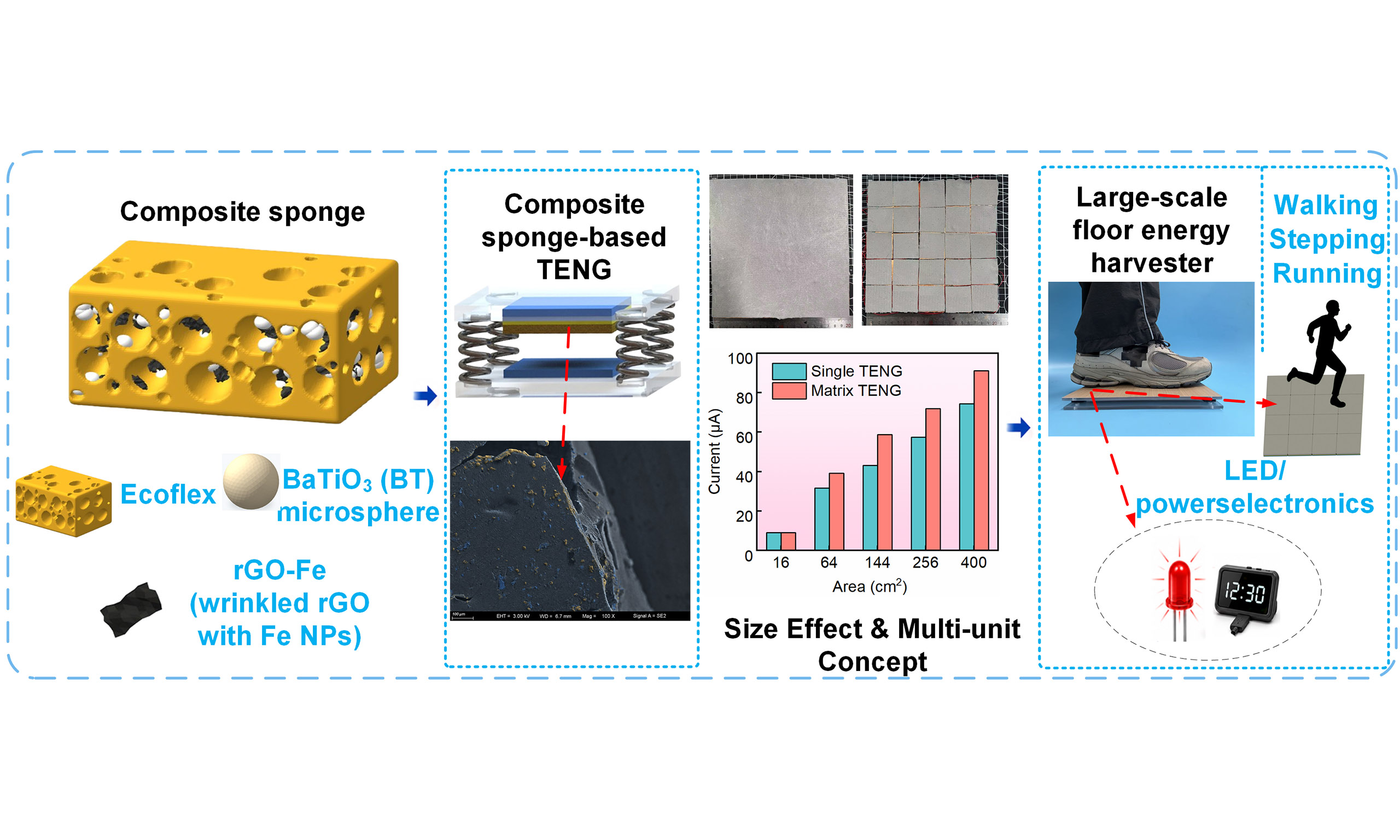
Keywords
INTRODUCTION
In recent years, the pursuit of sustainable energy has driven substantial advancements in energy harvesting technologies. To effectively harness renewable energy, researchers have devoted significant effort to the development of triboelectric nanogenerators (TENGs)[1]. Compared with electromagnetic and piezoelectric devices, TENGs exhibit higher output voltage due to their extremely low capacitance[2-4]. However, most current TENG devices remain relatively small, with triboelectric surfaces typically limited to the centimeter scale, which constrains their energy output in large-scale energy-harvesting applications[5-7]. Larger-area TENGs offer the advantage of higher output performance, yet they also face several challenges[8-10]. For instance, as the size of TENGs increases, issues such as incomplete contact and low spatial utilization efficiency may arise, thereby limiting their output performance. Additionally, traditional thin-film materials may also exhibit insufficient mechanical robustness, structural support, and wear resistance when scaled to larger dimensions[11,12]. These limitations render traditional thin-film materials unsuitable for the development of large-area TENGs. Therefore, the design of large-area TENGs for energy harvesting must strike a balance between stability and high output performance, which is essential for the practical application of self-powered systems.
Among various triboelectric materials, Ecoflex is commonly used as a negative triboelectric material due to its high electron affinity and flexibility[13-15]. Ecoflex exhibits excellent flexibility, processability, biocompatibility, and tunable mechanical properties, which collectively endow it with great potential to meet the demands of a wide range of complex application scenarios[16-18]. However, the low dielectric constant of Ecoflex limits the relative capacitance and electrical performance of pure Ecoflex-based TENGs. Increasing the effective permittivity of Ecoflex can contribute to improved electrical performance in TENGs. To address this limitation, researchers have enhanced the dielectric constant of the polymer through molecular design or introduced high-dielectric particles (e.g., BaTiO3 (BT), TiO2, and polyvinylidene fluoride)[19-23]. However, achieving the desired dielectric constant typically requires a high-volume fraction of fillers, which can compromise the comfort and flexibility of the composite material. Compared with dense Ecoflex counterparts, porous sponge-like Ecoflex exhibits better durability and elasticity[24,25]. The porous structure also increases the frictional surface area, induces additional charges, and enhances overall capacitance, thereby improving the output performance of TENGs[26-30]. These structural improvements collectively enhance the overall energy-harvesting efficiency of TENGs by increasing charge generation and transfer[31,32]. Moreover, optimizing the structural design of TENGs to maximize the contact area between dielectric materials is beneficial[33]. This can be achieved by employing multi-unit arrays or enlarging the size of individual TENG units[34]. A larger effective contact area facilitates greater charge transfer between the friction layers, typically resulting in higher output voltage[35,36].
In this work, a composite sponge was fabricated by incorporating reduced graphene oxide (rGO)-Fe and BT particles as functional fillers into the Ecoflex matrix. The main contributions and innovations are as follows: First, the effects of BT and rGO-Fe contents on the microstructure of the composite sponge material were experimentally investigated. The optimal conditions for the content of functional fillers in the composite material were selected to maximize the output. Second, the influence of the content of conductive filler rGO-Fe on the electrical output performance of the sponge material was studied. Thirdly, the integration of large-area TENGs was successfully tested in both a single large-sized TENG and a matrix of small-sized TENGs, and the energy output of different forms of large-area TENGs under various capacitive loads was investigated. Finally, a floor energy harvester was constructed and its feasibility in practical application was tested. These findings provide a possibility for the design and optimization of large-scale TENGs with great potential for energy-harvesting applications.
EXPERIMENTAL
Synthesis of rGO-Fe
rGO powder was purchased from Tanfeng Graphene Technology Co., Ltd. Nano-iron powder was purchased from Guangzhou Metallurgy Group, and its particle size was less than 0.5 μm. The rGO powder was dispersed in alcohol by ultrasound for 30 min, then Fe powder was added and stirred by ultrasound for
Fabrication of BT/Ecoflex/rGO-Fe composite sponge for triboelectric devices
BT powder was purchased from McLean (reagent manufacturer), and the nominal average particle size or particle size range of the manufacturer is 3 μm. Ecoflex 0030 was purchased from Smooth-On Inc. NaCl and granulated sugar were commercially obtained and used as sacrificial pore-forming agents. Firstly, BT powder was added to anhydrous ethanol with a purity of 99.8%, and probe ultrasonic equipment was used. The ultrasonic probe operated at 20 kHz with a rated power of 100 W, and sonication was performed for 1 h. Circulating cooling water was used in the ultrasonic process to reduce the temperature rise caused by long-term ultrasound. After ultrasonic treatment, the dispersion was continuously stirred at 30 rpm until the ethanol was completely volatilized. Subsequently, BT powder was added to the Ecoflex prepolymer. Components A and B of Ecoflex were mixed according to the mass ratio of 1:1, and the composites with BT content of 0, 5, 10 and 15 wt% were prepared. The BT mass fraction was calculated relative to the total mass of Ecoflex components A and B.
When preparing BT/Ecoflex/rGOFe composites, 2, 4 and 6 wt% rGOFe were dispersed in anhydrous ethanol, respectively, and treated under the same ultrasonic conditions for 1 h. Then, 10 wt% BT powder was added, mechanically stirred at 30 rpm for 30 min, and then fully mixed with Ecoflex prepolymer to obtain the 10BT/Ecoflex/rGOFe composite precursor.
NaCl or sugar particles were added to the composite precursor as sacrificial templates. The ratio of pore-forming agent to the total mass of Ecoflex A and B components is 1:1, and the mixture was stirred at 30 rpm for 20 min. Subsequently, the mixture was poured into a 20 cm × 20 cm mold and cured at 70 °C for 2 h.
The cured composite materials were cut into different dimensions according to the subsequent experiments. For the thickness- and composition-dependent measurements, 4 cm × 4 cm samples with thicknesses of 1 and 2 mm were prepared. Based on the optimization results, the 1-mm-thick composite sponge was selected for the subsequent rGO-Fe optimization and large-area TENG experiments. For the S-TENG experiments, composite sponge samples with lateral dimensions of 4 cm × 4 cm, 8 cm × 8 cm, 12 cm × 12 cm, 16 cm× 16 cm, and 20 cm × 20 cm were prepared, corresponding to nominal contact areas of 16, 64, 144, 256, and
Preparation of BT/Ecoflex/rGO-Fe composite film-based TENGs
TENGs can be prepared by using piezoelectric BT/Ecoflex and 10BT/Ecoflex/rGO-Fe composite films as the main triboelectric layer (triboelectric negative layer) and matching with Cu foil (triboelectric positive layer). Cu tape is attached to the rigid platform, while BT/Ecoflex and 10BT/Ecoflex/rGO-Fe composite films are attached to the Cu electrode; the electrodes are made on the Cu side, and then adhered to the acrylic substrate with double-sided tape. Subsequently, the two layers are installed on a linear motor to operate the contact-separation process.
Material characterizations
The microstructure of rGO-Fe mixed materials was studied by a field emission scanning electron microscope (Carl ZEISS AG, Sigma 300, Germany). Thermogravimetric analysis (TGA) was performed using the thermal analyzer NETZSCH TG 209 F3 (NETZSCH Scientific Instrument Trading Co., Ltd., Germany). The effective relative permittivity of the porous composites was measured by an impedance analyzer (1J65120BD1, Wayne Kerr Electronics Ltd., UK). The sample size was 4 cm × 4 cm × 1 mm, and it was placed between two parallel electrodes during the test. All samples were measured at 20 Hz-107 Hz and under the same environmental conditions. The effective relative permittivity was extracted from the measured capacitance using the specimen thickness and effective electrode area under the parallel-plate approximation. The reported values represent the effective relative permittivity of the entire porous specimen, including the solid skeleton and air-filled pores.
Measurement of triboelectric output performance
To characterize the electrical output of TENGs, a linear motor (Suzhou Corey Limo Motor Co., Ltd. Linmot, LinMot 1100, Zurich, Switzerland) is used, which can control the frequency and amplitude of motion through software. The real-time signal is measured by a programmable electrometer (Keithley Instrument Company, Keithley 6514, USA). We use a linear motor to provide excitation, and measure different groups of TENGs under fixed movement distance and acceleration. In addition, the current, voltage and charging speed of the capacitor are measured by an electrometer.
RESULTS AND DISCUSSION
Consideration of functional filling materials
We fabricated a TENG using the prepared composite sponge material [Figure 1A]. Barium titanate (BT) was employed as a ferroelectric functional filler, while sodium chloride was used as a sacrificial template within the Ecoflex matrix to construct a porous composite sponge with an enhanced dielectric response. Ecoflex was selected as the flexible polymer matrix due to its excellent elasticity, corrosion resistance, chemical stability, and compatibility with inorganic fillers. In addition, Ecoflex can be readily processed into various designed geometries, meeting the structural requirements of large-area and coplanar TENG configurations while maintaining a simple and environmentally friendly fabrication process.
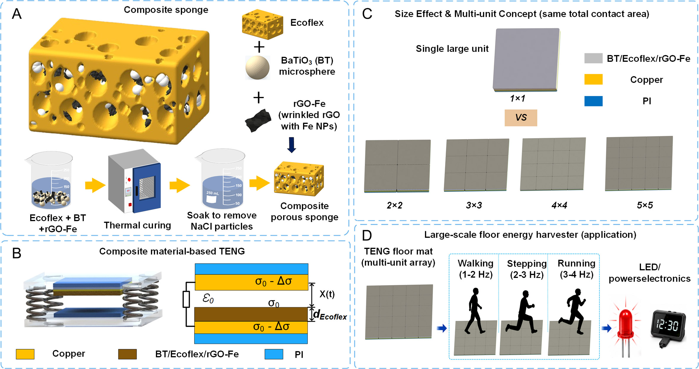
Figure 1. (A) Schematic diagram of the preparation of porous BT/Ecoflex/rGO-Fe composite film and Ecoflex composite sponge. (B) Schematic diagram and model of the TENG based on composite materials. (C) The size effect and multi-element design for the same total contact area. (D) Schematic illustration of large-area energy harvesting applications using a multi-element TENG mat array.
The incorporation of BT particles plays a critical role in regulating the interfacial charge behavior of the composite sponge. Owing to the high spontaneous polarization of BT, localized polarized domains can be generated within the Ecoflex matrix, which enhances the dielectric constant and facilitates the accumulation of induced charges at the triboelectric interface. Consequently, the charge-capturing capability of the friction layer is improved, resulting in an increased interfacial charge density and enhanced electrical output. Generally, the output performance of TENGs increases with the dielectric constant of triboelectric materials, as a higher dielectric constant facilitates stronger electrostatic induction and improved charge storage capability.
Furthermore, rGO exhibits a layered structure and abundant oxygen-containing functional groups. After incorporation with Fe nanoparticles, rGO-Fe domains are uniformly distributed within the Ecoflex matrix. These spatially distributed conductive domains may promote localized charge transfer during the contact-separation process and reduce charge dissipation during repeated charging and discharging cycles. More importantly, the coexistence of ferroelectric BT particles and conductive rGO-Fe networks induces a conductive-ferroelectric coupling effect. In this coupled system, BT provides strong spontaneous polarization and generates additional polarization-induced charges, whereas the rGO-Fe conductive network facilitates charge transport and trapping within the composite. The synergistic interaction between ferroelectric polarization and conductive charge transport effectively increases the induced charge density, thereby enhancing the triboelectric output performance.
The working principle of composite film-based TENGs
The working principle of the contact-separation mode TENG is schematically illustrated in Figure 1B. Owing to the different triboelectric polarities of the paired materials, electrons are transferred from the Cu layer to the Ecoflex-based composite during the contact electrification process. Consequently, negative charges are accumulated on the surface of the 10BT/Ecoflex/rGO-Fe dielectric layer, while positive charges remain on the Cu surface. In the initial equilibrium state, no potential difference exists between the two electrodes. When an external mechanical force is applied to the Cu film, the separation distance between the Cu film and the composite sponge layer gradually decreases until intimate contact is established. After the removal of the external force, the two layers begin to separate, resulting in the generation of an electric potential difference between the electrodes. This potential difference drives electrons to flow from the bottom electrode to the top electrode through the external circuit until electrostatic equilibrium is achieved, thereby generating a positive voltage pulse across the load resistor. The induced charge density on the lower Cu electrode is closely associated with the separation distance between the dielectric layer and the upper electrode. Upon the subsequent application of external force, the previously established electrostatic equilibrium is disrupted. As the separation gap decreases, the electrostatic field drives electrons to flow reversely from the upper electrode back to the lower electrode, and the device eventually returns to the fully compressed equilibrium state, producing a negative voltage pulse. Therefore, the repeated contact-separation motion continuously regulates the internal charge distribution of the TENG, enabling periodic electron transfer through the external circuit and generating a stable alternating electrical output. The size effect and multi-unit integration strategy are illustrated in Figure 1C, and the corresponding large-area floor energy-harvesting application is demonstrated in Figure 1D.
The electrical output of a TENG originates from the Maxwell displacement current. For a device operating in the contact-separation mode, the generated voltage can be expressed as follows[37]:
where σ0 denotes the triboelectric charge density of Ecoflex at a given contact state, while Δσ represents the transferred charge density on the Cu electrode; ε0 and εr correspond to the permittivity of free space and the relative permittivity of Ecoflex, respectively; X(t) describes the instantaneous gap between the two triboelectric layers, whereas dEcoflex and t denote the thickness and time associated with the Ecoflex film, respectively. According to this relationship, the TENG output is mainly governed by the surface charge density σ, induced charge, and dielectric permittivity of the friction material.
For contact-separation mode TENGs, the dielectric layer also affects the capacitance characteristics of the device. Under the parallel plate approximation, the maximum capacitance can be expressed as[4]:
where A is the effective electrode area, d is the dielectric layer thickness, ε0 is the vacuum permittivity, and εr is the effective relative permittivity of the dielectric layer. For a given electrode area and dielectric layer thickness, increasing the effective relative permittivity increases capacitance and helps enhance electrostatic induction and interfacial charge storage. However, the actual output of a TENG is influenced by surface charge density, dielectric response, contact state, separation distance, and charge transport behavior. Therefore, the effective relative permittivity is considered here as one contributing parameter to the output performance rather than its sole determinant.
Morphology of composite materials
Surface morphology images of pure Ecoflex, BT/Ecoflex, and BT/Ecoflex/rGO-Fe composite films are presented in Figure 2A-F. To provide more comprehensive morphological information, the cross-sectional scanning electron microscope (SEM) image of the BT/Ecoflex/rGO-Fe composite sponge is provided in Supplementary Figure 1. This cross-sectional observation complements the surface morphology analysis by revealing the internal structure of the composite material. For pure Ecoflex, the surface exhibits a smooth morphology without obvious particles or granules [Figure 2A], and the corresponding energy dispersive spectroscopy (EDS) spectrum confirms the presence of elements including C, Si, and O [Supplementary Figure 2]. After the incorporation of BT, particulate phases with a block-like morphology are observed within the Ecoflex matrix, as shown in the surface morphology of the BT/Ecoflex composite [Figure 2B]. The EDS spectrum indicates variations in elemental composition among different regions. In the BT/Ecoflex composite, Ba is the dominant element, followed by C and Si derived from the Ecoflex matrix, as shown in Supplementary Figure 3.
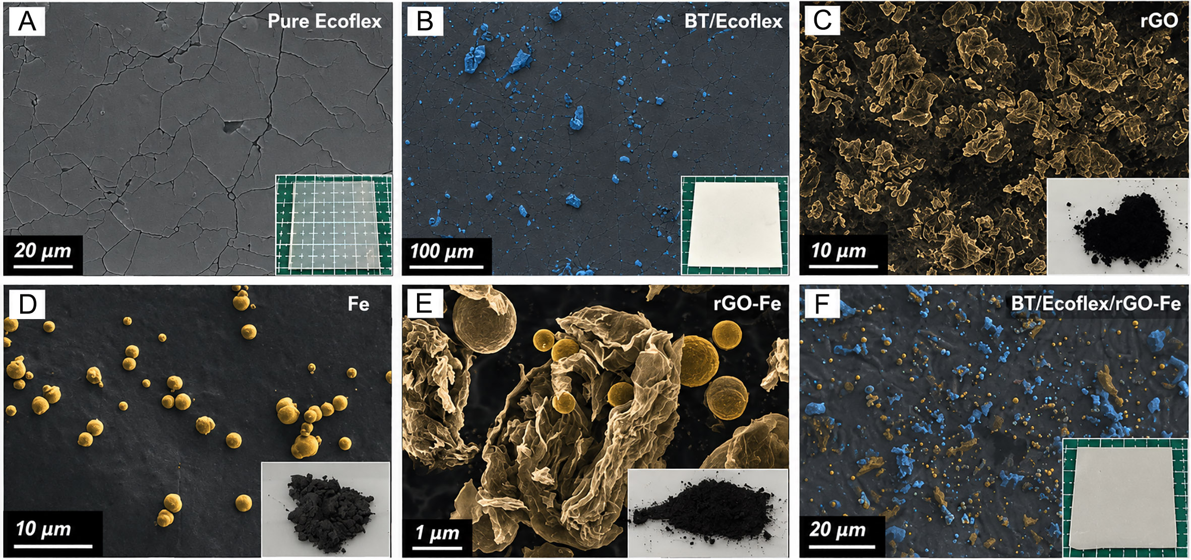
Figure 2. SEM of composite films with different functional fillers. (A) The surface morphology of pure Ecoflex. (B) The surface morphology of BT/Ecoflex. (C) The structural morphology of rGO. (D) The structural morphology of Fe. (E) The structural morphology of rGO-Fe. (F) The surface morphology image of BT/Ecoflex/rGO-Fe.
Figure 2C-E shows the structural morphologies of rGO and rGO-Fe observed by electron microscopy. As shown in these images, rGO exhibits a typical two-dimensional layered structure similar to graphene, accompanied by a large specific surface area, which is beneficial for applications such as catalyst supports and adsorbents. The surface morphology of the 10BT/Ecoflex composite film after the introduction of rGO-Fe is shown in Figure 2F. The incorporation of 0-6 wt% rGO-Fe into the 10BT/Ecoflex composite film improves the dispersion of fillers within the Ecoflex matrix. This improvement can be attributed to the two-dimensional sheet-like structure of rGO, which provides a large contact area for the interaction and distribution of Fe nanoparticles and BT between the rGO layers. The spatial confinement effect generated by this structure prevents direct contact and aggregation of the fillers, thereby enhancing their dispersion. FESEM combined with elemental mapping was further employed to evaluate the elemental distribution and dispersion within the 10BT/Ecoflex/rGO-Fe composite.
In summary, pure Ecoflex exhibits a relatively smooth morphology, whereas the introduction of BT results in the formation of dispersed particulate phases within the polymer matrix. rGO displays a typical wrinkled lamellar structure, Fe nanoparticles exhibit quasi-spherical morphologies, and the rGO-Fe hybrid presents characteristic Fe nanoparticles anchored onto rGO sheets. These observations demonstrate that conductive and ferroelectric phases can be effectively incorporated into the Ecoflex matrix to construct a stable hybrid microstructure. On the one hand, the high spontaneous polarization of BT enhances interfacial polarization and increases the induced charge density. On the other hand, the introduction of rGO-Fe provides localized sites for charge trapping and redistribution. The synergistic interaction between these two phases contributes to the formation of a conductive-ferroelectric coupling effect. For BT-doped Ecoflex matrix samples, Ba and Ti are mainly distributed in clustered regions, whereas Si, O, and C are widely distributed throughout the composite, as shown in Supplementary Figure 3. After the addition of rGO-Fe, the elemental distribution becomes more uniform, as demonstrated in Supplementary Figure 4. This result indicates that the presence of rGO promotes a more homogeneous dispersion of BT particles within the polymer matrix.
Additionally, to evaluate the thermal stability of the samples, we performed TGA on the composite sponge materials. The study involved heating the samples from room temperature to 800 °C at a rate of 10 °C/min in an air atmosphere to reflect real-world conditions. This experimental design allowed us to systematically assess the thermal stability of the samples over a wide temperature range. The results of the TGA for the different materials are presented in Supplementary Figure 5. The figure shows that all tested materials exhibited excellent thermal stability in air, being able to withstand temperatures up to 418 °C in practical environments without any significant weight loss. This indicates that these materials show good potential for applications in high-temperature environments.
Electrical output of BT/Ecoflex/rGO-Fe sponge TENGs
According to existing reports, porous structures enhance the output performance of TENGs by increasing the specific surface area of dielectric surfaces, enlarging the contact area for friction, inducing additional charges, and ultimately improving the capacitance[38,39]. Additionally, guided by Paschen’s law, the porous architecture regulates the microscopic electric-field distribution, alleviates local field concentration, and prolongs the effective breakdown pathway, thereby improving high-voltage stability under enlarged device dimensions. We prepared planar non-porous films and sponge films with different pore sizes by incorporating NaCl and sugar particles into pure Ecoflex, respectively. We fabricated TENGs with films of varying particle sizes and thicknesses and compared their triboelectric properties, with the experimental results shown in Supplementary Figure 6. These results indicate that sponge materials with porous structures significantly improve the triboelectric performance of TENGs, with those prepared using NaCl as a sacrificial template being particularly notable. When the thickness of the composite film was 1 mm, the output voltage and current of the film prepared using NaCl as the sacrificial template were 44.33% and 110.34% higher than those of the planar film, respectively.
The role of BT content in determining the triboelectric response was investigated using BT/Ecoflex porous composites containing 0-15 wt% BT. Each sample was cut into a 4 cm × 4 cm square and assembled with Cu electrodes of slightly reduced size. The dependence of ISC and VOC on BT loading is summarized in
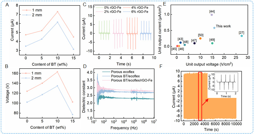
Figure 3. Output performance of small-size TENGs. (A) Output current of TENGs in contact-separation mode with different BT content. (B) Output voltage of TENGs in contact-separation mode with different BT content. (C) Output current of sponge composites with different rGO-Fe content. (D) Capacitance-derived effective relative permittivities of porous Ecoflex, BT/Ecoflex, and BT/Ecoflex/rGO-Fe composite sponges measured under identical conditions. (E) Comparison of the area-normalized output voltage and output current of the present TENG with those of previously reported TENGs. (F) Stability test of BT/Ecoflex/rGO-Fe composite films.
rGO is an effective dispersing agent, and its unique structure and properties play a crucial role in inhibiting particle aggregation, ensuring a more uniform dispersion of BT particles throughout the Ecoflex[40,41]. Furthermore, after the introduction of rGO-Fe, EDS mapping reveals spatially distributed elemental signals throughout the investigated region. The rGO-Fe filler is uniformly distributed within the Ecoflex matrix, which may facilitate localized charge transport. To investigate the influence of rGO-Fe content on the electrical output performance of BT/Ecoflex composite sponges, samples with different rGO-Fe concentrations (0, 2, 4, and 6 wt%) were prepared using the optimized BT content of 10 wt%, as shown in Figure 3C. As the rGO-Fe concentration increased from 0 to 4 wt%, the output current increased from 7.305 to 9.18 μA. However, with a further increase in rGO-Fe content from 4 to 6 wt%, both the output voltage and output current decreased from 254.92 V and 9.18 μA to 150.28 V and 7.03 μA, respectively.
Figure 3D presents a comparison of the capacitance-derived effective relative permittivity of porous Ecoflex, BT/Ecoflex, and BT/Ecoflex/rGO-Fe sponges measured under identical conditions. The obtained values represent the overall effective polarization and capacitance characteristics of the porous samples, which are determined by both the solid composite framework and the air-filled pores. The incorporation of 10 wt% BT slightly increases the effective relative permittivity from approximately 2.3 to 2.8. However, the further introduction of rGO-Fe does not result in a noticeable increase in the effective relative permittivity within the investigated loading range. This limited enhancement can be attributed to the relatively low volume fraction of BT, dielectric dilution caused by air-filled pores, and the spatial isolation of BT particles within the low-dielectric-constant Ecoflex matrix.
It should be noted that the effective relative permittivity presented in Figure 3D is specifically used to compare the polarization and capacitive response of the porous triboelectric layers, rather than to provide a comprehensive evaluation of their overall dielectric properties. Dielectric loss represents the dissipative component of the dielectric response and therefore has a different physical meaning from the capacitance-derived relative permittivity discussed above. Supplementary Note 1 further discusses the relationship between the real and dissipative components of dielectric response and the influence of porosity based on complex permittivity and effective dielectric models. Therefore, the enhancement mechanism of the TENG is discussed by correlating the dielectric response, triboelectric measurements, material morphology, and finite element simulations.
The increase in output voltage and output current can be explained as follows. The conductive rGO-Fe filler introduces spatially distributed conductive domains into the polymer matrix, which may provide localized sites for charge transport and is consistent with the observed improvement in electrical output. This high-mobility filler network is of significant importance for the performance improvement of TENGs[42]. However, when the content of rGO-Fe further increased from 4 to 6 wt%, the output voltage and output current dropped from 254.92 V and 9.18 µA to 150.28 V and 7.03 µA, respectively. The reduction in voltage and current of the BT/Ecoflex/rGO-Fe composite film is attributed to the agglomeration and percolation of nanofiller rGO-Fe within the polymer. As the content of rGO-Fe increases, rGO-Fe that cannot find corresponding dipoles in Ecoflex and BT particles generates a large number of additional free charges. Consequently, the free charges present within the composite material gradually turn the composite into a conductor. This detracts from the performance of the TENG devices, leading to a decrease in output voltage and current. Finite-element simulations were subsequently performed to further clarify the conductive-ferroelectric coupling mechanism under compression [Supplementary Figure 7]. Compared with porous Ecoflex and porous BT/Ecoflex, porous BT/Ecoflex/rGO-Fe exhibits more pronounced electric-field redistribution and localized polarization hotspots near heterogeneous interfaces. Under the compression strain of 30%, the average polarization amplitude of porous BT/Ecoflex is increased by 104.1%, and the electrostatic energy density is also increased by 7.0%. These results show that the BT phase enhances dielectric polarization, while rGO-Fe promotes the process of interfacial charge transfer and capture, which together promote the improvement of electromechanical response.
Furthermore, Figure 3E illustrates the electrical performance of TENGs fabricated from various porous polymer materials[27,43-50]. As indicated in Figure 3E, TENGs based on the BT/Ecoflex/rGO-Fe sponge achieve satisfactory electrical output performance. Considering that environmental humidity and long-term repeated trampling may affect the actual performance of the floor TENG, the output stability test and long-term cycle durability evaluation of the device under different humidity conditions are further carried out. The humidity experiment was carried out at the ambient temperature of 25 ± 2 °C, and the relative humidity was set to 37%, 46%, 57%, 68%, 76%, and 80% RH, respectively. In Supplementary Figure 8, the open-circuit voltage of the device changes with the ambient humidity. Under the highest test humidity of 80% RH, the voltage output remains at 50% of the initial value under the reference condition. This is because the adsorbed water layer increases the surface charge leakage and electrostatic shielding effect, thus reducing the effective surface charge density[49,51]. In order to evaluate the mechanical stability of the device under the condition of long-term repeated trampling, 30,000 continuous cycle tests were carried out at the driving frequency of 3 Hz. In Figure 3F, after 30,000 cycles, the output of the device still maintains satisfactory results, and the output waveform does not show obvious drift or distortion. After cyclic testing, no obvious structural fracture, permanent compression deformation or electrode delamination were observed, indicating that the porous composite structure has good cyclic durability and signal repeatability under indoor normal temperature and repeated mechanical loads[48].
Application of the BT/Ecoflex/rGO-Fe sponge material in large-size TENGs
Driven by the increasing demand for large-scale energy harvesting and self-powered systems, large-area TENGs have attracted growing research interest. Understanding the relationship between contact area and electrical output is essential for optimizing the structural design and improving the energy conversion efficiency of large-area TENGs. To systematically investigate the area-dependent output characteristics, two large-scale TENG configurations fabricated using different assembly strategies, namely a single large-area TENG and a small-scale parallel-array TENG, were evaluated under identical testing conditions. The electrical outputs of all TENG devices were measured using a linear reciprocating motion system driven by a linear motor. During the measurements, the contact-separation distance was set to 5 cm, the displacement amplitude was 5 cm, the operating frequency was 3 Hz, and the acceleration amplitude was 0.5 g
The electrical responses of the single large-area device (S-TENG) and the small-unit matrix device (M-TENG) are compared in Figure 4. Their assembly layouts are illustrated in Figure 4A, while optical images of TENGs with different sizes are provided in Supplementary Figure 9. For S-TENG, the total contact areas mentioned above correspond to individual complete triboelectric units measuring 4 cm × 4 cm, 8 cm × 8 cm, 12 cm × 12 cm, 16 cm× 16 cm and 20 cm × 20 cm, respectively. For the M-TENG, the size of each basic unit is fixed at 4 cm × 4 cm, with a unit area of 16 cm2, and array configurations of 1 × 1, 2 × 2, 3 × 3, 4 × 4 and
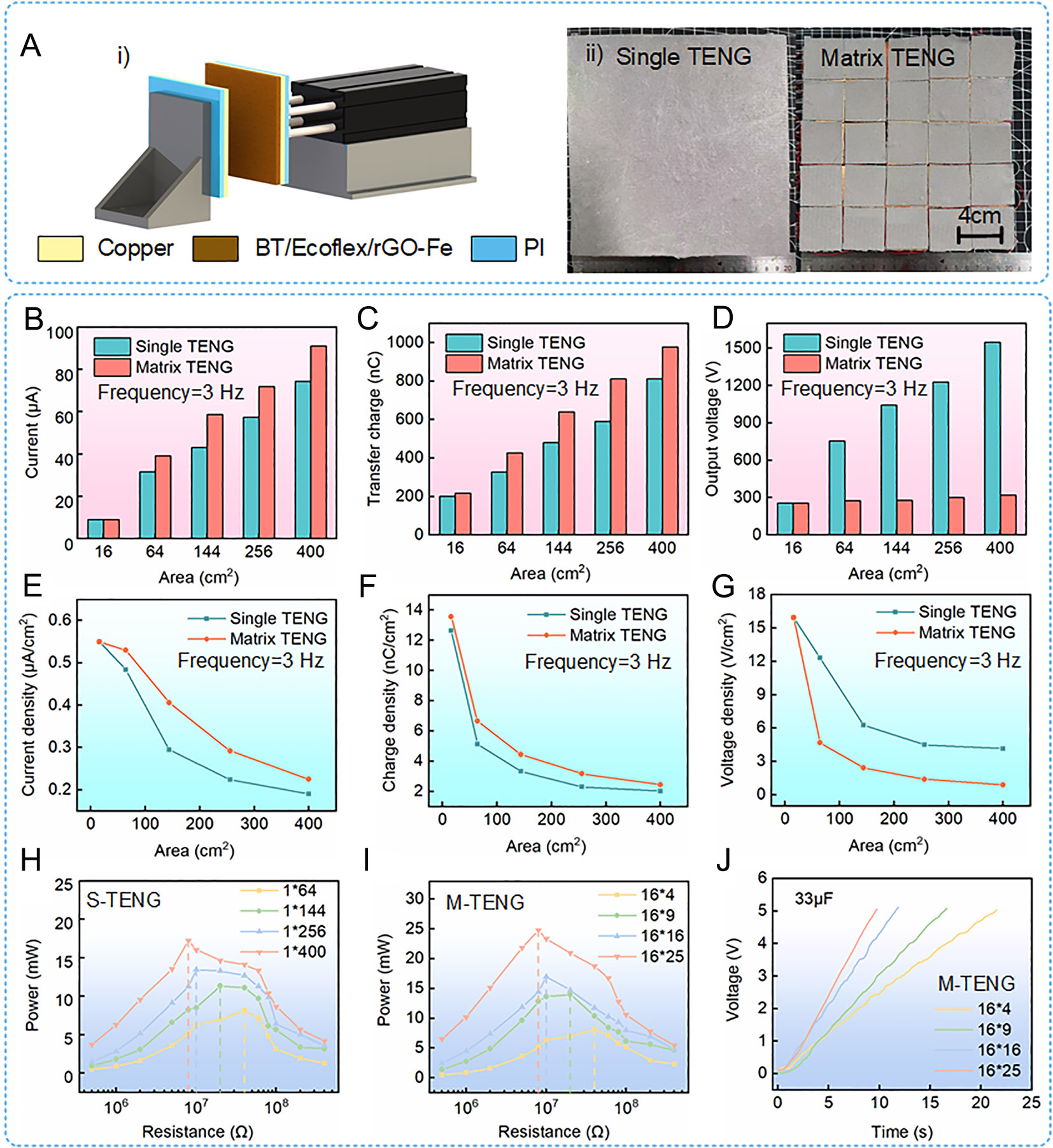
Figure 4. Comparison of electrical output performance between the S-TENG and M-TENG. (A) (i) schematic diagram of the experimental setup; (ii) integration modes of the S-TENG and M-TENG. (B) Current. (C) Transferred charge. (D) Output voltage. (E) Current density. (F) Charge density. (G) Voltage density. (H) Experimental results of matching resistance of the single TENG. (I) Experimental results of matching resistance of the matrix TENG. (J) Capacitance charging ability of the matrix TENG.
To clarify the influence of device dimensions and unit integration methods on electrical output performance, it is necessary to examine separately the dependence of open-circuit voltage, short-circuit current and charge transfer on contact area. For contact-separation mode TENGs, under the ideal parallel-plate approximation, the open-circuit voltage can be expressed as[37]:
Here, σ represents the effective surface charge density, x the contact-separation distance, and ε the permittivity of vacuum. This relationship indicates that, under ideal conditions where the surface charge density, dielectric structure and separation distance are constant, the open-circuit voltage does not increase linearly with the nominal contact area. Consequently, an increase in area does not necessarily result in a proportional increase in open-circuit voltage. The voltage variations actually measured may also be influenced by contact uniformity, parasitic capacitance, edge electric fields, local air gaps and the input impedance of the measurement system.
Unlike the open-circuit voltage, the charge transferred during a complete mechanical cycle is approximately proportional to the effective contact area:
Here, Anom represents the nominal contact area, ηc the effective contact coefficient, and ηq the charge collection and retention coefficient. Under ideal conditions of complete contact, ηc and ηq approach 1, and consequently the charge transfer increases with area. However, as the area of an individual device increases, variations in substrate flatness, pressure distribution and local deformation can lead to residual air gaps and incomplete contact, resulting in the effective contact area being less than the nominal area. Therefore, the charge transfer in large-area S-TENGs does not necessarily increase linearly with the nominal area.
Short-circuit current is the rate of change of charge transfer with respect to time[53]:
Consequently, the short-circuit current depends not only on the charge transferred during each cycle, but is also influenced by the operating frequency, the contact-separation speed, local contact synchronization and the signal waveform. For S-TENGs and M-TENGs with the same total nominal area, under ideal, uniform and fully synchronized contact conditions, both should theoretically generate approximately the same total transferred charge. Dividing the device into multiple units does not, in itself, generate any additional triboelectric charge or energy.
However, experimental results indicate that, under conditions of identical total nominal contact area and identical external mechanical loading, the M-TENG exhibits higher short-circuit current and charge transfer. This difference stems primarily from non-ideal effects during actual large-area contact. Compared with a single large-area S-TENG, the M-TENG comprises multiple smaller units with greater mechanical compliance. Each unit is able to adapt more effectively to localized pressure and surface deformation, thereby reducing ineffective contact areas caused by substrate warping, uneven pressure distribution and residual air gaps. Consequently, the M-TENG exhibits a higher average effective contact coefficient and charge collection efficiency.
To further clarify the area-dependent output behavior and identify an appropriate device configuration for high power density, the output normalized by contact area was evaluated: current density, charge density and voltage density, as shown in Figure 4E-G. With increasing total contact area, the normalized current density, charge density, and voltage density exhibited decreasing trends for both the S-TENG and M-TENG, with more pronounced reductions observed for the S-TENG. This decrease can be ascribed to the gradual accumulation of inactive contact regions as the device area increases, which lowers the energy conversion efficiency of the S-TENG. Therefore, the device design should balance energy conversion efficiency and power density according to the requirements of specific applications. For applications requiring high voltage output, a single-layer large-area structure is more suitable, whereas a small-area array configuration is preferred when a higher current output is desired.
Figure 4H and I show the load-matching results of the S-TENG and M-TENG, respectively. As the contact area increased, the maximum peak power of both configurations shifted toward lower load resistance, indicating a gradual decrease in the optimal load. This behavior is mainly attributed to the fact that a larger contact area promotes charge transfer, allowing the TENGs to reach optimal charge transport and power output at a lower external resistance. At a contact area of 400 cm2, the peak powers of the S-TENG and M-TENG reached 17.24 and 23.35 mW, respectively. The higher peak power of the M-TENG can be explained by its faster increase in output current with increasing contact area compared with the S-TENG. Although open-circuit voltage and instantaneous peak power are frequently used in academic studies to evaluate TENG performance, open-circuit operation is uncommon in practical applications; therefore, relying solely on these indicators may lead to an incomplete assessment.
The charging rates of additional large-area TENG configurations were compared, as shown in Supplementary Figure 10. Based on this, we further explored the capacitive charging behavior of TENGs to demonstrate their true output performance, as shown in Figure 4J and Supplementary Figure 10B. Under excitation of 0.5 g and 3 Hz, different areas of TENGs were used to charge a 33 μF capacitor to 5 V. For the S-TENG and M-TENG with a contact area of 64 cm2, it took 30 and 22 s, respectively, to charge the 33 μF capacitor to 5 V. When the contact area was 400 cm2, the S-TENG and M-TENG took 15 and 10 s, respectively, to charge the 33 μF capacitor to 5 V. As the contact area increased, the charging power increased significantly. Additionally, under the same area condition, the charging speed of the M-TENG was consistently higher than that of the S-TENG. This is because in a single large-area TENG, the charges are mainly concentrated in the contact region. However, due to the large area, the charge distribution is relatively dispersed, which may lead to lower charge transfer efficiency. In contrast, in multiple small-area TENGs connected in parallel, the charge distribution in each small-area unit is more concentrated, resulting in higher charge transfer efficiency. Detailed parameters of the capacitors and rectifier bridges are provided in Supplementary Note 2. In order to clarify the physical source of the improved charging performance of the capacitor, an equivalent circuit model was established, as shown in Supplementary Note 3. Overall, the total output power of both TENG configurations increased with increasing contact area. However, because of structural constraints, the S-TENG exhibited lower overall energy conversion efficiency than the M-TENG. Therefore, when the two configurations had the same maximum contact area, the M-TENG delivered higher energy conversion efficiency and greater total output energy.
To demonstrate the practical applicability of the M-TENG, a 20 cm × 20 cm floor-based energy harvester was fabricated using the M-TENG structure [Figure 5A]. In Figure 5B, sponges were introduced into the prototype to separate the two triboelectric layers, enabling mechanical energy generated by walking or running on the floor to be harvested. The repeated human motion induced continuous contact-separation cycles between the friction layers, thereby producing a stable electrical output, as shown in Figure 5C and D. During walking, the device delivered a maximum ISC of 73 μA and a transferred charge of 740 nC. Under running conditions, the maximum short-circuit current and transferred charge increased to 128 μA and 1,053 nC, respectively.
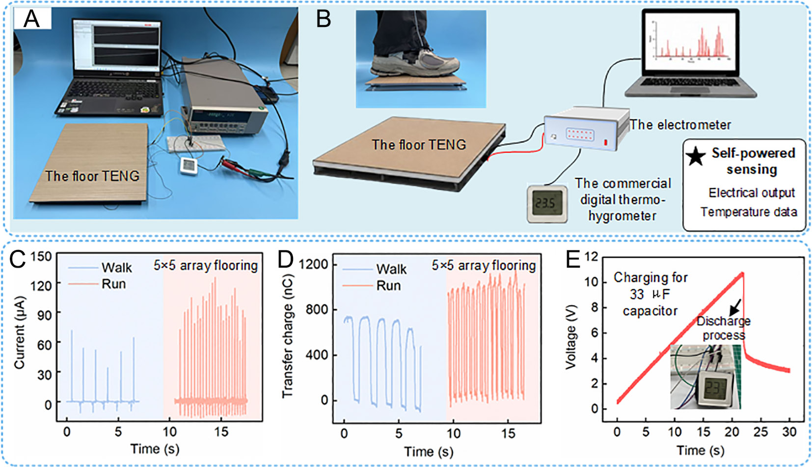
Figure 5. Application of the M-TENG floor energy harvester for biomechanical energy harvesting and powering a commercial digital thermo-hygrometer. (A and B) The floor energy harvester is used to supply power to the hygrometer. (C and D) Output current and transferred charge generated when pedestrians walk or run on the floor. (E) The process by which the floor energy harvester supplies energy for the commercial digital thermo-hygrometer during running.
To further verify the actual power-supply capability of the floor-mounted energy harvester, the alternating current generated by the M-TENG was bridge-rectified and stored in a capacitor. As shown in
CONCLUSION
In this study, we developed a readily fabricated hierarchical porous composite sponge material to realize scalable TENGs with enhanced charge density. rGO-Fe and BT particles were incorporated as conductive-ferroelectric hybrid fillers into an Ecoflex matrix to construct composite sponge-based TENGs. Initially, the effects of BT concentration and dielectric thickness on the microstructure and electrical output performance of the composite sponge were systematically investigated. Benefiting from the high spontaneous polarization of BT, the charge capture ability of the frictional interface was effectively improved. When the sponge size was 4 cm × 4 cm, the thickness was 1 mm, and the BT concentration was 10 wt%, the device achieved a peak VOC of 168.66 V and a peak ISC of 7.305 μA.
Subsequently, rGO-Fe was introduced as a conductive filler into the BT/Ecoflex sponge to further enhance charge transport and trapping. As the rGO-Fe concentration increased from 0 to 4 wt%, the output voltage increased from 168.66 to 254.92 V, and the output current increased from 7.305 to 9.18 μA. This improvement is consistent with a possible synergistic contribution of BT and rGO-Fe. BT may enhance local polarization and interfacial charge storage, whereas the spatially distributed rGO-Fe domains may provide localized sites for charge transport and charge retention within the porous composite. As a result, the induced charge density and output performance of the TENG were significantly enhanced.
Furthermore, to explore an effective scaling-up strategy for large-area TENGs, we fabricated both a single large-scale TENG and an array-based multi-unit TENG using the optimized composite sponge material, and compared their energy outputs under various capacitive and resistive load conditions. When the contact area was 400 cm2, the peak power of the S-TENG and M-TENG reached 17.24 and 23.35 mW, respectively. The results demonstrate that, under the same total contact area, smaller-sized multi-unit TENG arrays can generate more energy than larger-sized single-cell TENGs. This indicates that the multi-unit design can alleviate the limitations caused by size scaling, improve output stability, and provide a feasible route for large-scale TENG integration. Finally, a floor energy harvester was constructed to evaluate the practical application potential of the proposed hierarchical porous scaled-up TENGs. The device successfully harvested mechanical energy from different pedestrian gaits, demonstrating its feasibility for self-powered sensing and energy harvesting in intelligent home ecosystems.
DECLARATIONS
Authors’ contributions
Data curation, investigation, writing - original draft: Cao, C.
Writing - review & editing: Shen, F.; Zhang, Q.; Zheng, Q.; Zhou, J.; Xie, X.
Conceptualization: Guo, H.
Resources, supervision, writing - review & editing, visualization: Peng, Y.
Supervision, methodology, writing - review & editing: Li, Z.
Availability of data and materials
The data supporting the findings of this study are available within this Article and its Supplementary Materials. Further data are available from the corresponding authors upon request.
AI and AI-assisted tools statement
During the preparation of this manuscript, ChatGPT (GPT-5.6 Sol, released 2026-07-09; OpenAI) was used solely for English-language polishing, grammar correction, and improvement of textual clarity and consistency. The tool did not influence the study design, data collection, analysis, interpretation, or the scientific content of the work. All AI-assisted revisions were carefully reviewed and verified by the authors. All authors take full responsibility for the accuracy, integrity, and final content of the manuscript.
Financial support and sponsorship
This work was funded by the National Natural Science Foundation of China (No.: 62473246), the National Natural Science Foundation of China (No.: 62225308), and Shanghai Rising-Star Program (Grant No. 24QA2702700).
Conflicts of interest
All authors declared that there are no conflicts of interest.
Ethical approval and consent to participate
In this study, the participants were involved solely in non-invasive engineering demonstrations of the TENG energy-harvesting floor under normal stepping or walking conditions. No human biological samples, health information, or other human research data were collected, and all measurements were performed solely to evaluate device performance. In accordance with Article 2 of the Measures for Ethical Review of Science and Technology (Trial) [Guo Ke Fa Jian (2023) No. 167], and based on the Institutional Statement on the Applicability of Engineering Demonstration and Ethical Review issued by the School of Future Technology at Shanghai University, this component of the study does not require formal ethical review approval. Informed consent was obtained from all participants involved in the study.
Consent for publication
Not applicable.
Copyright
© The Author(s) 2026.
Supplementary Materials
REFERENCES
1. Ali, N. U. H. L.; Pazhamalai, P.; Sathyaseelan, A.; Dongale, T. D.; Kim, S. A self-integration via dual-active mode structural-SC-TENG energy device for electrochemical energy storage and triboelectric energy harvesting. Appl. Energy. 2024, 376, 124265.
2. Cui, X.; Nie, J.; Zhang, Y. Recent advances in high charge density triboelectric nanogenerators. Int. J. Extrem. Manuf. 2024, 6, 042001.
3. Li, C.; Bai, Y.; Shao, J.; Meng, H.; Li, Z. Strategies to improve the output performance of triboelectric nanogenerators. Small. Methods. 2024, 8, 2301682.
4. Cao, C.; Li, Z.; Shen, F.; et al. Progress in techniques for improving the output performance of triboelectric nanogenerators. Energy. Environ. Sci. 2024, 17, 885-924.
5. Li, Y.; Guo, Z.; Zhao, Z.; et al. Multi-layered triboelectric nanogenerator incorporated with self-charge excitation for efficient water wave energy harvesting. Appl. Energy. 2023, 336, 120792.
6. Wang, J.; Jiang, Z.; Sun, W.; Xu, X.; Han, Q.; Chu, F. Yoyo-ball inspired triboelectric nanogenerators for harvesting biomechanical energy. Appl. Energy. 2022, 308, 118322.
7. Qin, H.; Li, Q.; Lu, D.; Lin, J.; Gao, W.; Wang, H. Triboelectric-memristive coupling for self-powered neuromorphic computing: mechanisms, devices, and systems. Energy. Mater. 2026, 6, 28.
8. Wang, H. L.; Kuang, S. Y.; Li, H. Y.; Wang, Z. L.; Zhu, G. Large-area integrated triboelectric sensor array for wireless static and dynamic pressure detection and mapping. Small 2019, 16, 1906352.
9. Cao, H.; Ru, Q.; Fang, D.; et al. A freestanding rotating triboelectric nanogenerator with large area and high efficiency for triboelectric plasma CO2 reduction. Chem. Eng. J. 2024, 489, 150798.
10. Zhang, X.; Wang, Y.; Liu, M.; Cao, Y.; Chen, S.; Cao, D. Nonlinear dynamical modeling and response analysis of complex structures based on assumed mode weighting. Eng. Struct. 2024, 312, 118226.
11. Akram, W.; Sun, Z.; Qu, Z.; et al. A hierarchical core-shell tribopositive yarn TENG with electrospun polyethyleneimine (PEI) nanofibers for sustainable energy harvesting and human machine interface application. Mater. Today. Energy. 2026, 55, 102162.
12. Rastegardoost, M. M.; Tafreshi, O. A.; Ghaffari-Mosanenzadeh, S.; Park, C. B.; Naguib, H. E. Ultra-lightweight aerogel-fibrous material with high thermal stability and boosted triboelectricity for crack detection in harsh environments. Mater. Today. Energy. 2026, 56, 102221.
13. Shrestha, K.; Sharma, S.; Pradhan, G. B.; et al. A siloxene/ecoflex nanocomposite-based triboelectric nanogenerator with enhanced charge retention by MoS2/LIG for self-powered touchless sensor applications. Adv. Funct. Mater. 2022, 32, 2113005.
14. Ramadasu, G.; Woo, I.; Yoon, J. U.; Gajula, P.; Bae, J. W. ZnSnO3-ecoflex/LDH-PU based triboelectric nanogenerator for motion-activated battery-free smart street lighting. Small 2026, 22, e10831.
15. Zhao, J.; Xiao, Y.; Yang, W.; et al. Ultrastretchable triboelectric nanogenerators based on ecoflex/porous carbon for self-powered gesture recognition. Adv. Mater. Technol. 2023, 8, 2201769.
16. Chen, S. W.; Huang, S. M.; Wu, H. S.; et al. A facile, fabric compatible, and flexible borophene nanocomposites for self-powered smart assistive and wound healing applications. Adv. Sci. 2022, 9, 2201507.
17. Hou, Y.; Zhang, H.; Zhou, K. Ultraflexible sensor development via 4D printing: enhanced sensitivity to strain, temperature, and magnetic fields. Adv. Sci. 2024, 12, 2411584.
18. Zhai, K.; Wang, H.; Ding, Q.; et al. High-performance strain sensors based on organohydrogel microsphere film for wearable human-computer interfacing. Adv. Sci. 2022, 10, 2205632.
19. Zhong, Y.; Wang, J.; Wu, L.; et al. Dome-conformal electrode strategy for enhancing the sensitivity of BaTiO3-doped flexible self-powered triboelectric pressure sensor. ACS. Appl. Mater. Interfaces. 2023, 16, 1727-36.
20. Chakraborty, I.; Wu, M.; Lai, S.; Lai, C. Self-powered broadband photodetection with mixed-phase black TiO2-assisted output boosting of a biobased triboelectric nanogenerator. Chem. Eng. J. 2023, 452, 139138.
21. Hu, Y.; Wang, Y.; Tian, S.; Yu, A.; Wan, L.; Zhai, J. Performance-enhanced and washable triboelectric air filter based on polyvinylidene fluoride/UiO-66 composite nanofiber membrane. Macromol. Mater. Eng. 2021, 306, 2100128.
22. Zhang, H.; Wang, K.; Li, J.; Li, J.; Zhang, R.; Zheng, Y. Liquid-based nanogenerator fabricated by a self-assembled fluoroalkyl monolayer with high charge density for energy harvesting. Matter 2022, 5, 1466-80.
23. Kim, J.; Lee, J. H.; Ryu, H.; et al. High-performance piezoelectric, pyroelectric, and triboelectric nanogenerators based on P(VDF-TrFE) with controlled crystallinity and dipole alignment. Adv. Funct. Mater. 2017, 27, 1700702.
24. Kocaman Kabil, F.; Oral, A. Y. Influence of the pore size on optical and mechanical properties of ecoflex sponges. Mater. Res. Express. 2024, 11, 035305.
25. Rana, S. M.; Faruk, O.; Selim Reza, M.; Robiul Islam, M.; Kim, H.; Yeong Park, J. All porous Ecoflex and SEBS-based stretchable high-performance triboelectric nanogenerator for self-powered human activity monitoring. Chem. Eng. J. 2024, 488, 151050.
26. So, S.; Park, S.; Park, S.; Gwak, G.; Lyu, S. Additive-manufactured flexible triboelectric sensor based on porous PDMS sponge for highly detecting joint movements. Int. J. Precis. Eng. Manuf. Green. Technol. 2022, 10, 97-107.
27. Biutty, M. N.; Koo, J. M.; Zakia, M.; Handayani, P. L.; Choi, U. H.; Yoo, S. I. Dielectric control of porous polydimethylsiloxane elastomers with Au nanoparticles for enhancing the output performance of triboelectric nanogenerators. RSC. Adv. 2020, 10, 21309-17.
28. Luo, S. H.; Samad, Y. A.; Chan, V.; et al. Cellular graphene: fabrication, mechanical properties, and strain-sensing applications. Matter 2019, 1, 1148-202.
29. Zheng, Q.; Fang, L.; Guo, H.; et al. Highly porous polymer aerogel film-based triboelectric nanogenerators. Adv. Funct. Mater. 2018, 28, 1706365.
30. Liu, T.; Zhao, Z.; Liang, R.; et al. Tough and elastic anisotropic triboelectric materials enabled by layer-by-layer assembly. Adv. Funct. Mater. 2025, 35, 2500207.
31. Park, C.; Song, G.; Cho, S. M.; et al. Supramolecular-assembled nanoporous film with switchable metal salts for a triboelectric nanogenerator. Adv. Funct. Mater. 2017, 27, 1701367.
32. Rana, S. M. S.; Zahed, M. A.; Rahman, M. T.; et al. Cobalt-nanoporous carbon functionalized nanocomposite-based triboelectric nanogenerator for contactless and sustainable self-powered sensor systems. Adv. Funct. Mater. 2021, 31, 2105110.
33. Choi, Y. S.; Kim, S. W.; Kar-Narayan, S. Materials-related strategies for highly efficient triboelectric energy generators. Adv. Energy. Mater. 2021, 11, 2003802.
34. Guan, Y.; Li, X.; Wei, Z.; et al. Bistable multi-layer triboelectric nanogenerator for harvesting random and ultra-low-frequency vibration energy with increased charge transfer. Adv. Sci. 2025, 12, e05246.
35. Sun, J.; Jeong, S.; Zheng, Z.; et al. Enhanced positive charge performance in triboelectric series: molecular engineering of conjugated mesoporous fibers for machine learning-based wearable sensors. Small 2024, 21, 2404737.
36. Jiao, Y.; Lin, Z.; Ma, X.; et al. High-performance triboelectric nanogenerators based on blade-coating lead halide perovskite film and electrospinning PVDF/graphene nanofiber. Chem. Eng. J. 2024, 483, 149442.
37. Niu, S.; Wang, Z. L. Theoretical systems of triboelectric nanogenerators. Nano. Energy. 2015, 14, 161-92.
38. Pharino, U.; Sinsanong, Y.; Pongampai, S.; et al. Influence of pore morphologies on the mechanical and tribo-electrical performance of polydimethylsiloxane sponge fabricated via commercial seasoning templates. Radiat. Phys. Chem. 2021, 189, 109720.
39. Chen, J.; Guo, H.; He, X.; et al. Enhancing performance of triboelectric nanogenerator by filling high dielectric nanoparticles into sponge PDMS film. ACS. Appl. Mater. Interfaces. 2015, 8, 736-44.
40. Konios, D.; Stylianakis, M. M.; Stratakis, E.; Kymakis, E. Dispersion behaviour of graphene oxide and reduced graphene oxide. J. Colloid. Interface. Sci. 2014, 430, 108-12.
41. Kaftelen-Odabaşı, H.; Odabaşı, A.; Caballero-Briones, F.; Arvizu-Rodriguez, L. E.; Özdemir, M.; Baydoğan, M. Effects of polyvinylpyrrolidone as a dispersant agent of reduced graphene oxide on the properties of carbon fiber-reinforced polymer composites. J. Reinf. Plast. Compos. 2022, 42, 1039-53.
42. Bisht, N.; Vishwakarma, J.; Jaiswal, S.; et al. Synergizing chemistry: unveiling the potential of hybrid fillers for enhanced performance in shape memory polymers. Adv. Compos. Hybrid. Mater. 2024, 8, 7.
43. Basith, S. A.; Chandrasekhar, A. Synergistic effect of dual surface modified ecoflex polymer for dynamic triboelectric nanogenerator towards sustainable battery-free tally counter. Adv. Mater. Technol. 2023, 8, 2300495.
44. Liu, Y.; Zheng, Y.; Wu, Z.; et al. Conductive elastic sponge-based triboelectric nanogenerator (TENG) for effective random mechanical energy harvesting and ammonia sensing. Nano. Energy. 2021, 79, 105422.
45. Kou, H.; Wang, H.; Cheng, R.; et al. Smart pillow based on flexible and breathable triboelectric nanogenerator arrays for head movement monitoring during sleep. ACS. Appl. Mater. Interfaces. 2022, 14, 23998-4007.
46. Long, S.; Feng, Y.; He, F.; et al. Biomass-derived, multifunctional and wave-layered carbon aerogels toward wearable pressure sensors, supercapacitors and triboelectric nanogenerators. Nano. Energy. 2021, 85, 105973.
47. Panpho, P.; Phetphong, P.; Charoonsuk, T.; Vittayakorn, N.; Sriwong, C.; Sumang, R. Enhanced performance of hybrid piezo/triboelectric using BaTiO3/polymer composite film modified with rGO. Polym. Plast. Technol. Mater. 2024, 63, 1745-54.
48. Lu, Y.; Qin, Q.; Meng, J.; et al. Constructing highly flexible dielectric sponge for enhancing triboelectric performance. Chem. Eng. J. 2023, 468, 143802.
49. Hao, Y.; Zhang, Y.; Mensah, A.; Liao, S.; Lv, P.; Wei, Q. Scalable, ultra-high stretchable and conductive fiber triboelectric nanogenerator for biomechanical sensing. Nano. Energy. 2023, 109, 108291.
50. Sun, J.; Tu, K.; Büchele, S.; et al. Functionalized wood with tunable tribopolarity for efficient triboelectric nanogenerators. Matter 2021, 4, 3049-66.
51. Liu, L.; Liu, H.; Fan, Z.; et al. Simultaneous solar-driven interfacial evaporation and photo-fenton oxidation by semiconducting metal-organic framework from waste polyimide. Energy. Environ. Mater. 2024, 8, e12812.
52. Yin, P.; Aw, K. C.; Jiang, X.; et al. Fish gills inspired parallel-cell triboelectric nanogenerator. Nano. Energy. 2022, 95, 106976.
Cite This Article
 Open Access
How to Cite
Download Citation
Export Citation File:
Type of Import
Tips on Downloading Citation
Citation Manager File Format
Type of Import
Direct Import: When the Direct Import option is selected (the default state), a dialogue box will give you the option to Save or Open the downloaded citation data. Choosing Open will either launch your citation manager or give you a choice of applications with which to use the metadata. The Save option saves the file locally for later use.
Indirect Import: When the Indirect Import option is selected, the metadata is displayed and may be copied and pasted as needed.
About This Article
Copyright

Data & Comments
Data
0








Comments
Comments must be written in English. Spam, offensive content, impersonation, and private information will not be permitted. If any comment is reported and identified as inappropriate content by OAE staff, the comment will be removed without notice. If you have any queries or need any help, please contact us at support@oaepublish.com.