



Polyethylene glycol with hydroxylated ammonium polyphosphate flame-retardant phase change composites for thermal storage
 0
0 Abstract
Efficient thermal management remains a key challenge in lithium-ion battery systems, as temperature fluctuations can compromise performance and safety. Composite phase change materials (CPCMs) offer high latent heat and passive temperature regulation but are often hindered by leakage and flammability. In this study, a passive battery thermal management system incorporating an intrinsically flame-retardant CPCM was developed. Hydroxylated ammonium polyphosphate (HAPP) was synthesized through a cation-exchange reaction and integrated into a hexamethylene diisocyanate (HDI)-crosslinked polyethylene glycol (PEG) network, providing structural support and flame-retardant functionality. A Polyethylene glycol (PEG)/Hexamethylene diisocyanate (HDI)/HAPP/expanded graphite (EG) composite, denoted as PHHE, was prepared through chemical crosslinking. The resulting three-dimensional HAPP-PEG-HDI network effectively restricted the macroscopic leakage of PEG. PHHE exhibits an initial latent heat of 111.35 J/g and a mass retention of 99.88% after aging at 80 °C for 5 h. During battery-module testing at a discharge rate of 2 C, the PHHE-based battery module reached a maximum temperature of 52.08 °C, indicating its passive temperature-regulation capability. These results demonstrate that PHHE integrates thermal-energy storage, shape stability, flame-retardant functionality, and battery temperature regulation, providing a potential material approach for the thermal management of battery packs and related energy-storage systems.
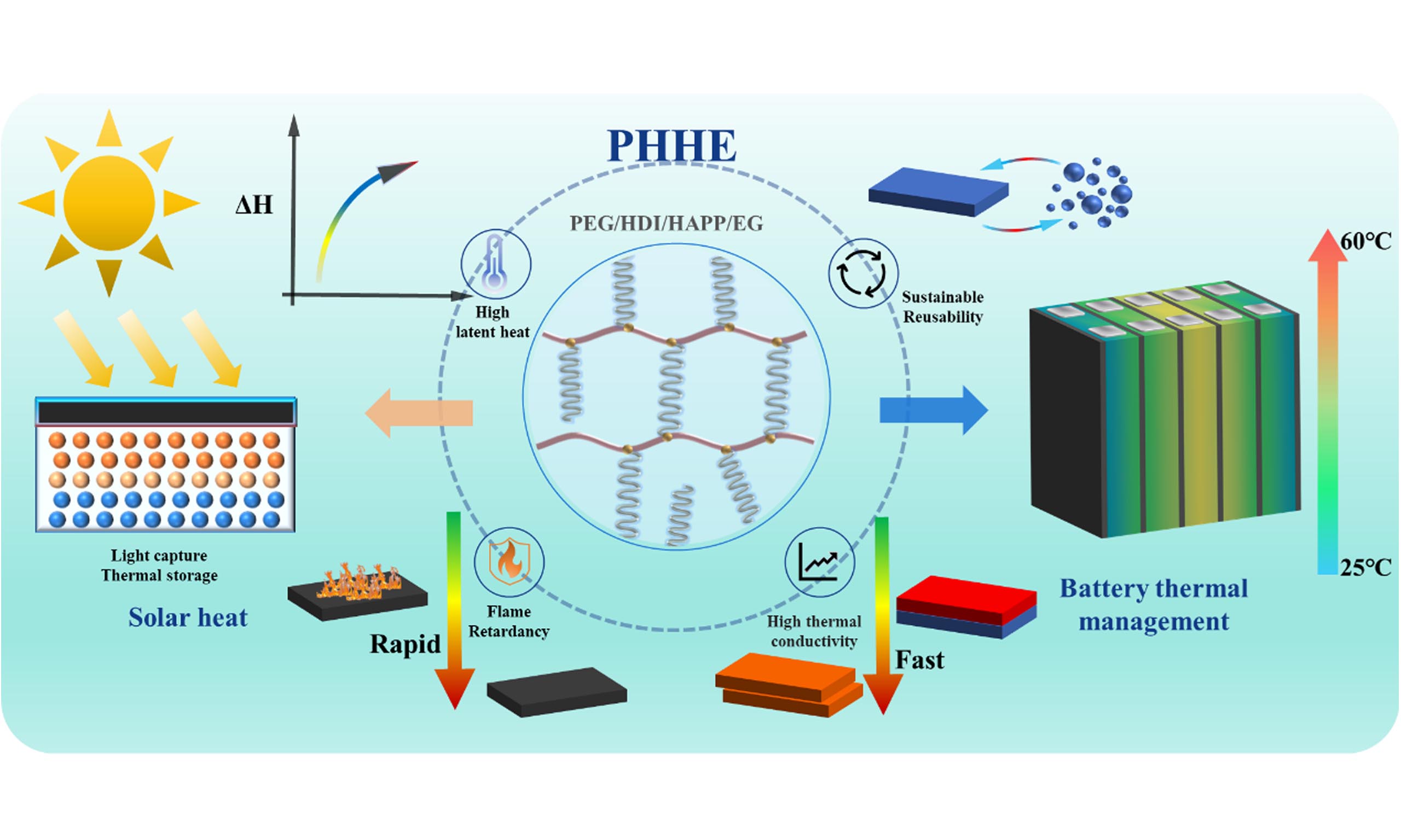
Keywords
INTRODUCTION
In recent years, the global energy transition has driven an urgent need for the efficient utilization of renewable energy sources[1-3]. Solar energy and electricity, as two pivotal forms of clean energy, constitute key enablers of future sustainable development[4,5]. The efficient capture and conversion of solar energy, whether through photovoltaic generation or photothermal utilization, are crucial for expanding its practical applications[6,7], while the stable, efficient, and safe use of electricity, particularly in mobile energy storage systems such as electric vehicles, is essential for realizing its full potential[8,9]. Nonetheless, both solar-energy and battery systems face major thermal management challenges. The photovoltaic conversion efficiency of solar cells deteriorates markedly with rising temperature[10]. Concurrently, solar thermal systems face the dual challenge of mitigating the inherent intermittency of solar irradiation and reconciling the temporal mismatch between energy supply and demand[11]. Meanwhile, heat accumulation during the charging and discharging of high-energy-density lithium-ion batteries presents a substantial risk of thermal runaway, posing a serious safety concern for electric vehicles and other electrical devices[12,13]. At the cell level, the development of high-energy-density lithium batteries has been accompanied by increasing safety challenges, motivating continuous efforts to improve battery stability and operational safety[14]. At the module level, flame-retardant Composite phase change materials (CPCMs) integrating latent-heat storage and high-temperature heat absorption have recently been developed to regulate battery temperature during normal operation and suppress thermal-runaway propagation under abuse conditions[15]. Therefore, the development of materials that combine efficient thermal management, energy storage, and thermal-safety regulation is of paramount importance for enhancing the reliability of the entire energy chain, from generation to end use[16,17].
Owing to their high latent heat and stable phase-change characteristics, organic phase-change materials (PCMs), such as paraffin and polyethylene glycol (PEG), are considered ideal media for thermal energy management and storage[18,19]. However, traditional PEG-based PCMs face inherent limitations, such as component leakage during the solid-liquid phase transition[20,21], low heat transfer efficiency[22,23], weak solar-spectrum absorption[24,25], and flammability[26,27], which have severely hindered their practical application in high-power-density battery systems. Physical blending can partially address these limitations of PEG-based PCMs. For example, composites with silica[28], hydrogels[29], or mica[30] can mitigate PEG leakage; the introduction of expanded graphite (EG) or aluminum nitride[31] as thermally conductive fillers can enhance thermal conductivity; titanium carbide[32] or oxygenated graphene[33] can improve photothermal conversion efficiency; and the addition of magnesium hydroxide[34] or ammonium polyphosphate (APP)[35] can improve flame retardancy. Although physical blending can alleviate some drawbacks of PEG-based PCMs, it frequently causes phase separation and weak interfacial interactions. These issues compromise shape stability and degrade performance during thermal cycling[36]. Furthermore, the effectiveness of physical blending is constrained by filler loading, as high filler contents often lead to a considerable reduction in latent heat[37]. In addition, the absence of a chemically encapsulated network surrounding PEG means that these CPCMs still undergo solid-liquid phase transitions[38], increasing the risk of leakage during long-term cycling.
Polyurethane-based PCMs represent an effective strategy for chemically encapsulating PEG. Chen et al. successfully prevented PCM leakage by reacting PEG with isophorone diisocyanate (IPDI), thereby producing a material with solid-solid phase-transition behavior rather than the solid-liquid phase transition of pure PEG[39]. Shi et al. prepared polyurethane-carbon nanotube composites through in situ polymerization of PEG and hexamethylene diisocyanate (HDI). By adjusting the molecular weight of PEG and the crosslinking density, highly flexible PCMs were obtained[40]. Zhang et al. synthesized phase-change polyurethane through the reaction of PEG and N,N-dihydroxyethyl aniline with IPDI, incorporating modified carbon nanotubes as thermally conductive fillers to obtain a flexible and shape-stable composite[41]. Zhou et al. used vacuum impregnation to create polyurethane-based solid-solid PCMs integrated with halloysite nanotube-grafted graphene aerogel[42]. The resulting composites demonstrated high latent heat, excellent thermal stability and reliability, efficient photothermal and electrothermal conversion, and promising potential for energy storage applications. Bai et al. incorporated PEG and tetrabromobisphenol A into a polyurethane backbone, producing inherently flame-retardant solid-solid PCMs with phase-change capability, self-healing behavior, and recyclability[43].
Although PEG/diisocyanate-based solid-solid PCMs and APP/EG-containing flame-retardant CPCMs have been reported, several limitations remain[44]. In most APP-containing systems, APP is physically blended into the polymer matrix and acts only as a flame-retardant filler, which may result in weak interfacial interactions, filler migration, and phase separation. Meanwhile, conventional PEG/HDI crosslinked systems mainly focus on leakage prevention and shape stability, without integrating a reactive phosphorus-nitrogen flame-retardant component into the chemical network. Moreover, increasing the loading of physically incorporated flame retardants and thermally conductive fillers may reduce the PEG content and latent heat. Therefore, it remains challenging to construct a CPCM that simultaneously maintains latent heat storage, leakage resistance, thermal conductivity, char-forming capability, and battery thermal-management performance through a chemically integrated structure.
In this research, hydroxyl-functionalized ammonium polyphosphate (HAPP) was synthesized via a cation-exchange reaction between APP and 3-aminopropanol[45] to serve as a reactive phosphorus-nitrogen flame retardant. Distinct from physically blended APP, HAPP bears reactive hydroxyl groups capable of copolymerizing with HDI and PEG. Consequently, HAPP functions dually as a structural node within the PEG/HDI/HAPP crosslinked network and as a char-forming flame-retardant agent. This covalently integrated architecture effectively suppresses the macroscopic flow of PEG during phase transitions and enhances the interfacial compatibility between the phosphorus-rich moieties and the polymer matrix. To further augment thermal transport, EG was incorporated to establish efficient heat-transfer pathways[46]. The primary innovation of this work resides in the synergistic integration of a reactive HAPP-derived flame-retardant network with an EG-based thermal-conductivity network-moving beyond mere physical blending of PEG/HDI or APP/EG. As a result, the optimized PHHE (PEG/HDI/HAPP/EG) composite achieves a high latent heat of 111.35 J/g, a mass retention of 99.88%, a thermal conductivity of 1.547 W/(m·K), and a total heat release (THR) of 95.69 MJ/m2. The comprehensive, multiscale evaluation ranged from material characterization to module-level testing and was performed to assess its phase-change behavior, anti-leakage properties, thermal transport efficiency, combustion resistance, photothermal conversion capability, and battery thermal management performance. A comparison with previously reported PEG-based CPCMs is provided in Supplementary Table 1.
EXPERIMENTAL
Materials
Polyethylene glycol (molecular weight 2000) was procured from Guangzhou Najie Technology Co., Ltd., while hexamethylene diisocyanate was obtained from Guangzhou Muran Biochemical Technology Co., Ltd. Expanded graphite was acquired from Qingdao Tengda Co., Ltd., and ammonium polyphosphate was purchased from Guangzhou Rentai Technology Co., Ltd. 3-aminopropanol was procured from Guangzhou Simi Biotechnology Co., Ltd., while anhydrous ethanol was obtained from Guangzhou Baijun Technology Co., Ltd.
Preparation of CPCM
As demonstrated in Figure 1, HAPP was synthesized through a cation-exchange reaction between APP and 3-aminopropanol. Briefly, 300 mL of ethanol, 13.5 mL of deionized water, and 10.47 g of 3-aminopropanol were added to a 500 mL three-necked flask and stirred at room temperature for 10 min at 300 rpm. Subsequently, 45 g of APP was added, and the mixture was refluxed at 90 °C for 4 h under a nitrogen atmosphere. After cooling, the precipitate was filtered, washed three times with anhydrous ethanol, and vacuum-dried at 80 °C to a constant weight.
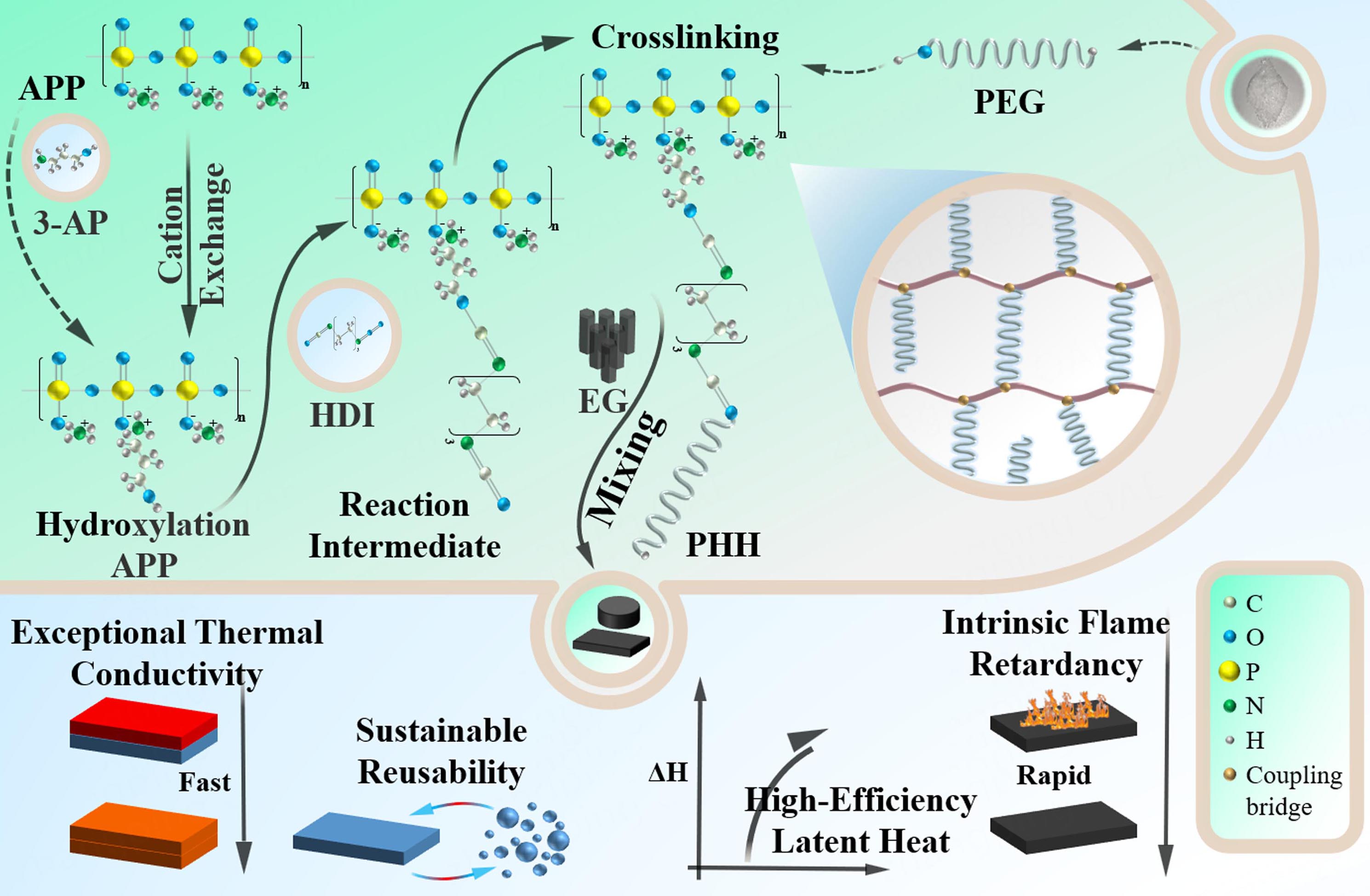
Figure 1. Schematic illustration of the formation, crosslinked structure, and multifunctional properties of PHHE. PHHE: PEG/HDI/HAPP/EG; APP: ammonium polyphosphate; PEG: polyethylene glycol; HDI: hexamethylene diisocyanate; EG: expanded graphite; PHH: PEG/HDI/HAPP; HAPP: hydroxylated ammonium polyphosphate.
The hydroxyl functionality of HAPP was theoretically estimated from the feed molar ratio of 3-aminopropanol to the APP repeating units. The molar amounts of 3-aminopropanol and APP repeating units were 0.1394 and 0.4639 mol, respectively, corresponding to a nominal functionalization degree of approximately 30.0 mol%. Assuming complete incorporation of 3-aminopropanol and the introduction of one hydroxyl group per molecule, the feed-based theoretical hydroxyl content of HAPP was estimated to be 2.513 mmol/g. In the nominal formulation calculation, one terminal hydroxyl group per PEG2000 molecule was regarded as the effective reactive hydroxyl group. Accordingly, the molar ratio of HAPP-derived hydroxyl groups, HDI-derived isocyanate groups, and effective PEG-derived hydroxyl groups was designed as 1:2:1.
The CPCMs were prepared by reacting HDI with HAPP and PEG. Pre-dried PEG was maintained at 80 °C, followed by the sequential addition of HAPP and EG with mechanical stirring at 600 rpm for 30 and 60 min, respectively. HDI was then added, and the mixture was continuously stirred at 600 rpm for 12 h before being transferred into a mold for curing.
Table 1 displays the ratios of the different CPCM components. The number of hydroxyl groups on HAPP is calculated by the ratio of 3-aminopropanol to APP; the ratio of isocyanate groups on HDI to these hydroxyl groups is 2:1. This enables the excess isocyanate groups to react with PEG and convert it into PHHE. In CPCMs, HAPP provides support as the hard segment, PEG provides latent heat as the soft segment, and HDI serves as a bridge between the two. To study the application of HAPP in CPCMs, the samples were named PH (PEG/HDI), PHA (PEG/HDI/APP), PHH (PEG/HDI/HAPP), PHE (PEG/HDI/EG), PHAE (PEG/HDI/APP/EG), and PHHE, respectively, based on whether APP and EG were added.
Composition ratios of different CPCMs
| Sample | PEG2000 (wt%) | HAPP (wt%) | APP (wt%) | HDI (wt%) | EG (wt%) |
| PH | 92.24 | - | - | 7.76 | - |
| PHE | 87.63 | - | - | 7.37 | 5 |
| PHA | 77.94 | - | 15.51 | 6.55 | - |
| PHAE | 74.05 | - | 14.73 | 6.22 | 5 |
| PHH | 77.94 | 15.51 | - | 6.55 | - |
| PHHE | 74.05 | 14.73 | - | 6.22 | 5 |
Instruments and characterization
Chemical and microstructural characterization
The crystalline structure of the CPCM was analyzed using X-ray diffraction (XRD; Rigaku D/max-2550) with Cu Kα radiation. Measurements were carried out in the 2θ range of 10° to 70° at a scanning rate of 10°/min. Functional group analysis was conducted via Fourier-transform infrared spectroscopy (Bruker Tensor-27) across 400-4,000 cm-1, using KBr-pelletized samples. Microstructural features, including the distribution of thermally conductive fillers (HAPP and EG), were observed with scanning electron microscopy (SEM; Hitachi S-3400 N, Japan) at an accelerating voltage of 20 kV. Through SEM image analysis, the dispersion state of HAPP and EG in CPCMs and their impact on the microstructure of the material can be intuitively understood.
Thermodynamic characterization
Phase change behavior, specifically latent heat, was characterized using a differential scanning calorimeter (DSC; Q20, TA Instruments Inc.). Approximately 8 ± 0.1 mg samples were heated from 30 °C to 80 °C at
Shape stability and thermal stability
The shape stability of the CPCM was evaluated using a constant-temperature heating stage (Dongguan Jinfeng Electronics Co., Ltd.). Circular specimens (35 mm in diameter and 10 mm in height) were subjected to isothermal conditioning at 80 °C for 5 h. Macroscopic heating-cooling cycling was also conducted between 30 and 80 °C in a temperature-controlled chamber, with a heating rate of 3 °C/min. The sample mass and appearance were examined after 100 cycles. Post-treatment mass measurements (M1) were conducted using a precision electronic balance (Shenzhen Botu Electronics Technology Co., Ltd.; resolution: 0.001 g). The mass retention rate (R) was subsequently calculated according to Equation 1:
Flame retardant performance test
As illustrated in Figure 2A, Cylindrical specimens with a diameter of 35 mm and a height of 10 mm were prepared from each CPCM formulation for flame-torch tests. Surface ignition was induced by exposing samples to a butane flame torch for 30 s, and flame-retardant behavior was qualitatively assessed via visual observation.

Figure 2. (A) LOI and CONE test platform of CPCM module; (B) Schematic diagram of the battery thermal management system platform. LOI: Limiting oxygen index; CONE: cone calorimetry; CPCM: composite phase change material.
For quantitative combustion analysis, cone calorimetry was performed on a VOUCH 6810 instrument following ISO 5660 standards. Square specimens with 100 mm × 100 mm × 4 mm were pre-conditioned at 25 ± 2 °C and 50 ± 5% relative humidity for 48 h prior to testing. Experiments were conducted under an external heat flux of 35 kW/m2. Key parameters, including heat release rate (HRR), peak HRR (PHRR), THR, smoke production rate (SPR), peak SPR (PSPR), and total smoke production (TSP), were continuously recorded. Due to the limited batch size of the synthesized CPCMs, each formulation was tested once; thus, the reported data serve as representative values for comparative evaluation, and statistical error bars are not provided.
The limiting oxygen index (LOI) was measured using a digital oxygen index meter (Model J-007, Jiangsu) according to ASTM D2863, employing rectangular specimens with 120 mm × 6.5 mm × 3 mm, as depicted in Figure 2A. Post-combustion analysis included photographic documentation of residual chars. Selected char residues were further examined by SEM to elucidate the underlying flame-retardant mechanisms.
Optical characterization and simulated solar irradiation test
To evaluate the optical absorption properties of the CPCM across the solar spectrum (250-2,500 nm), a ultraviolet- visible- near-infrared (UV-vis-NIR) spectrophotometer (UV-3600 Plus, SHIMADZU) was employed. The surface temperature at the center of the CPCM samples was recorded using a thermal infrared camera (FLIR, Therma CAM SC3000) connected to a computer during photothermal conversion experiments. The apparent photothermal conversion efficiency, defined as the proportion of incident light energy stored as latent heat, was calculated using the following equation:
where m is the sample mass, ΔHm is the melting enthalpy measured by DSC, I is the incident light intensity, A is the irradiated area, and Δt is the time required for each sample to pass through its own phase-transition temperature range. The phase-transition ranges were determined from the corresponding DSC curves, and the values of Δt were obtained from the temperature-time curves by linear interpolation.
Battery thermal management system test
The thermal regulation efficacy of CPCM was evaluated using custom-assembled battery modules comprising five series-connected LiFePO4 lithium-ion cells (specifications detailed in Table 2). As illustrated in Figure 2B, the experimental platform integrated a battery testing system (BTS-NTF, Shenzhen Neware Electronics Co., Ltd.), dedicated data acquisition software, and an Agilent 34970A multifunction unit for continuous temperature monitoring. Prior to testing, the battery module was placed in an environmental chamber at 25 °C and 0% relative humidity for 12 h to reach a stable state. Cycling tests were conducted separately at discharge rates of 1 C, 1.5 C, and 2 C. For each discharge rate, the battery module was first charged using a constant current-constant voltage protocol at 1 C, followed by a 0.5 h rest period for thermal equilibration. The module was then discharged at the designated rate (1 C, 1.5 C, or 2 C), followed by another 0.5 h rest period. This charge-discharge procedure was repeated for five consecutive cycles at each discharge rate to evaluate the thermal stability of the battery module under prolonged cycling conditions.
Parameters of batteries and battery modules
| Parameter | Single battery | CPCM-integrated module |
| Positive electrode | LiFePO4 | LiFePO4 |
| Negative electrode | Graphite | Graphite |
| Dimension (mm) | 20.5(L)*100(D)*140(H) | 132.5(L)*100(D)*140(H) |
| Nominal capacity (Ah) | 30 | 30 |
| Nominal voltage (V) | 3.2 | 16 |
| Charging voltage (V) | 3.65 | 18.25 |
| Discharge ending (V) | 2 | 10 |
RESULTS AND DISCUSSION
Chemical and microstructure characterization
By analyzing the Fourier Transform Infrared Spectroscopy (FTIR) spectra of APP and HAPP [Figure 3A], it can be observed that after the cation exchange reaction of 3-aminopropanol and APP, new peaks emerge in the HAPP spectrum[45]. The peak at 3,384 cm-1 is assigned to the stretching vibration of the OH group, indicating the successful introduction of hydroxyl groups into HAPP. The weak absorption features at 2,897 and 2,828 cm-1 are attributed to the stretching vibrations of -(CH2)3-, while the peak at 1,627 cm-1 corresponds to the bending vibration of protonated amino groups. These characteristic changes collectively support the successful synthesis of HAPP.
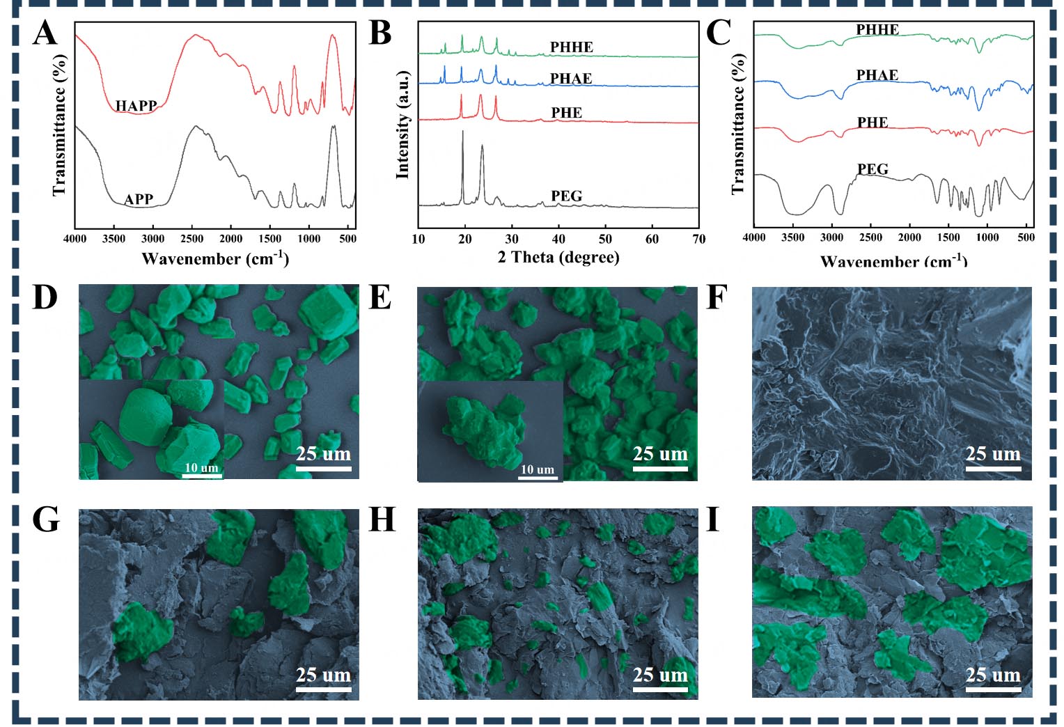
Figure 3. Structural and morphological characterization of the samples: (A) FTIR spectra of APP and HAPP; (B) FTIR spectra of PEG and the different CPCMs; (C) XRD patterns of PEG and the different CPCMs; SEM images of (D) APP, (E) HAPP, (F) PEG, (G) PHE, (H) PHAE, and (I) PHHE. The insets in (D) and (E) show enlarged views of APP and HAPP, respectively. The green regions were pseudo-colored to enhance particle visibility. HAPP: Hydroxylated ammonium polyphosphate; APP: ammonium polyphosphate; PEG: polyethylene glycol; PHAE: PEG/HDI/APP/EG; HDI: hexamethylene diisocyanate; EG: expanded graphite; CPCMs: composite phase change materials; XRD: X-ray diffraction; SEM: scanning electron microscopy; PHE: PEG/HDI/EG; PHHE: PEG/HDI/HAPP/EG; FTIR: fourier transform infrared spectroscopy.
Figure 3B compares the FTIR spectra of PEG and the various CPCMs. Upon curing, the hydroxyl groups of PEG and HAPP undergo polycondensation with the isocyanate groups of HDI to form urethane linkages. Compared with pristine PEG, all cured CPCMs display a characteristic carbonyl (C=O) stretching band at 1,700-1,707 cm-1 and an amide-II band at 1,533-1,552 cm-1, the latter arising from the coupled N-H bending and C-N stretching vibrations of the urethane bonds. Critically, the absence of a discernible absorption band near 2,270 cm-1 confirms the complete consumption of -NCO groups. While the broad absorption spanning 3,200-3,600 cm-1 persists, it now comprises overlapping contributions from residual O-H stretches, the newly formed urethane N-H groups, and extensive hydrogen-bonding interactions. Collectively, these spectral features substantiate the successful construction of the PEG/HDI-based polyurethane network and validate the covalent integration of HAPP into the crosslinked architecture.
Further evidence for the structural evolution is provided by the XRD patterns in Figure 3C. The incorporation of EG introduces a distinct diffraction peak at 26.59° [Supplementary Figure 1], while APP contributes characteristic peaks at 14.75° and 15.63°. Notably, upon replacing APP with HAPP, these characteristic peaks diminish in intensity and shift marginally to 14.90° and 15.78°, respectively. This attenuation and angular shift suggest that the HAPP-mediated crosslinking disrupts the ordered packing of crystalline domains, thereby reducing the overall crystallinity of the composite. Therefore, these XRD results provide independent, complementary support for the formation of the proposed crosslinked network.
SEM images of the CPCM microstructures are shown in Figure 3D-I. The micrograph of APP [Figure 3D] shows a granular morphology. After hydroxylation functionalization, HAPP exhibits noticeable particle aggregation [Figure 3E]. As depicted in Figure 3F, the microscopic appearance of PEG exhibits a smooth surface, which is attributed to partial melting or induced by electron-beam irradiation during the imaging process. The incorporation of EG into the PH system induces marked microstructural evolution in PHE
Thermodynamic properties and stability analysis
The influence of PEG/HDI/HAPP crosslinked networks on CPCM latent heat was investigated via DSC analysis [Figure 4A and B]. The phase-change enthalpy values are reported as the mean ± standard deviation of three independent measurements (n = 3), as summarized in Supplementary Table 2, with the corresponding error bars shown in Figure 4B. Pure PEG exhibited a phase change enthalpy of 164.25 J/g, while the PH showed a lower latent heat of 131.75 J/g because of its reduced PEG content and the restriction of PEG-chain crystallization by the urethane network. After incorporating APP, the latent heat of PHA decreased to 107.04 J/g. In contrast, PHH exhibited a higher latent heat of 119.75 J/g at the same PEG content of 77.94 wt%, indicating that the HAPP-containing network preserves the phase-transition capability of PEG more effectively than the APP-containing network. Following the incorporation of EG, these EG-containing CPCMs, namely PHE, PHAE, and PHHE, exhibited further reductions in latent heat due to decreased PEG content. Notably, PHHE maintained a latent heat of 111.35 J/g, exceeding that of PHAE, 92.04 J/g, at a comparable PEG content of 74.05 wt%.
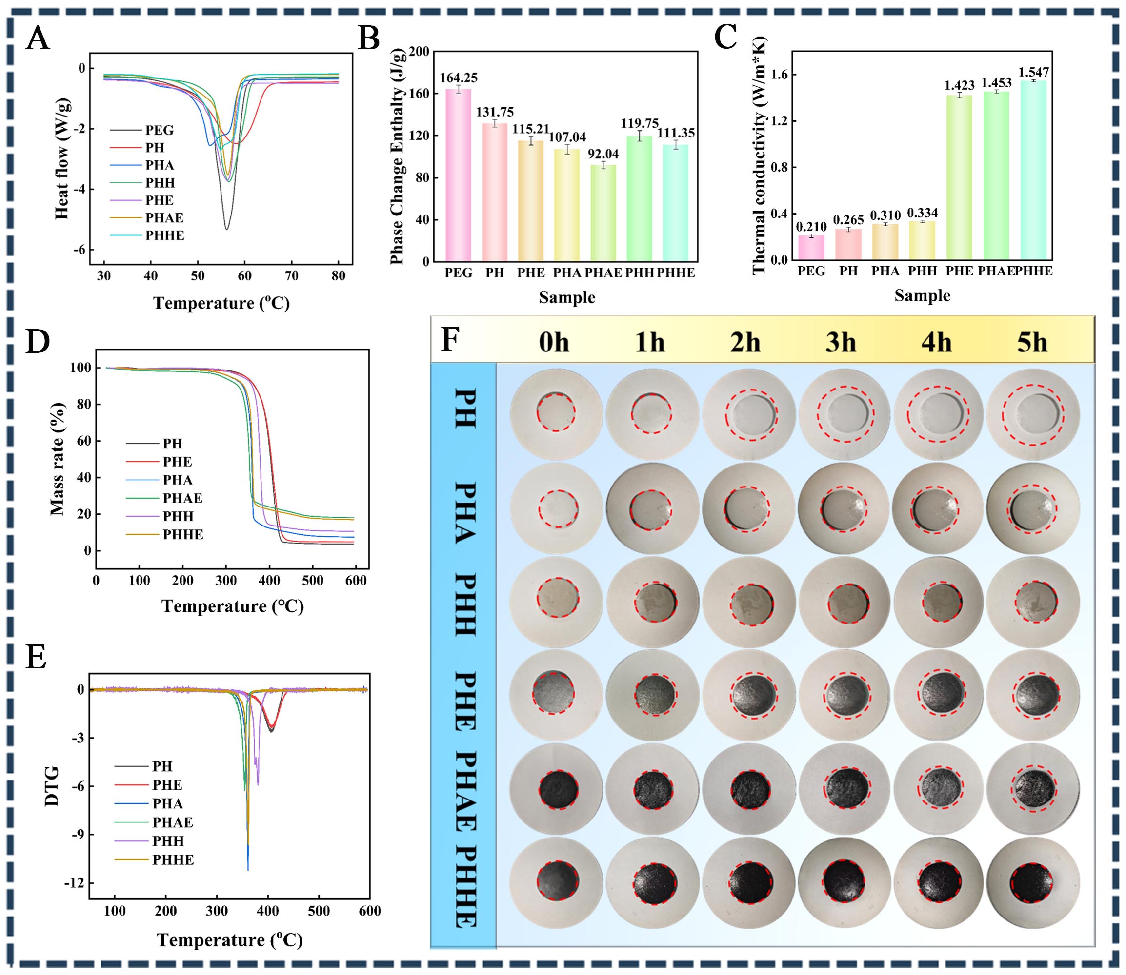
Figure 4. Thermal properties and shape stability of different samples: (A) DSC curves; (B) phase-change enthalpy values; (C) thermal conductivity; (D) TG curves; (E) DTG curves; and (F) anti-leakage performance at 80 °C. The error bars in (B) and (C) represent standard deviations from three repeated measurements, n = 3. PEG: Polyethylene glycol; PH: PEG/HDI; PEG: polyethylene glycol; HDI: hexamethylene diisocyanate; PHA: PEG/HDI/APP; APP: ammonium polyphosphate; PHH: PEG/HDI/HAPP; HAPP: hydroxylated ammonium polyphosphate; PHE: PEG/HDI/EG; EG: expanded graphite; PHAE: PEG/HDI/APP/EG; PHHE: PEG/HDI/HAPP/EG; DSC: differential scanning calorimeter; DTG: derivative thermogravimetric; TG: thermogravimetric.
Further information on the crystallization behavior was obtained from the DSC cooling curves in Supplementary Figure 2, and the corresponding crystallization parameters are summarized in Supplementary Table 3. All samples exhibited a distinct exothermic peak in the range of approximately 20-40 °C, corresponding to the crystallization of PEG segments. Compared with pure PEG, the CPCMs showed shifted and broadened peaks, indicating that the crosslinked networks and functional components altered PEG nucleation and restricted its ordered packing. The incorporation of EG caused composition-dependent changes in crystallization rather than a uniform decrease in crystallization temperature. PHHE retained a relative crystallinity of 93.12%, higher than that of PHAE (76.15%), which is consistent with its higher latent heat. This trend confirms that the crosslinked network not only affects the melting behavior but also influences the crystallization process, collectively governing the overall phase-change performance of the CPCMs.
The long-term phase-change stability of PHHE was further evaluated through 100 heating-cooling cycles. As shown in Supplementary Figure 3 and Supplementary Table 4, the specific PHHE specimen used for the cycling test exhibited an initial melting enthalpy of 111.97 J/g, which falls within the range defined by one standard deviation of the mean value obtained from three independent measurements (111.35 ± 4.32 J/g; Supplementary Table 2). After 100 cycles, its melting enthalpy decreased only slightly to 111.19 J/g, corresponding to an enthalpy retention of 99.30%. Meanwhile, the melting peak temperature remained nearly unchanged at approximately 54.3 °C, indicating favorable phase-transition stability under the tested cycling conditions.
To assess the influence of the crosslinked network on the thermal conductivity of the CPCMs, Figure 4C compares the thermal conductivities of the different samples. Before EG incorporation, PEG, PH, PHA, and PHH exhibited relatively low thermal conductivities because heat transfer was mainly governed by the low-conductivity polymer matrix. The difference between PEG and PH is attributed to the change in phase-change morphology caused by chemical crosslinking. The resulting chain-like network facilitates phonon transport and thereby increases the thermal conductivity[47]. Compared with PH, incorporating APP in PHA introduces additional solid heat-transfer bridges, while the difference between PH and PHH is related to their distinct crosslinked network structures. The HAPP-containing network provides more continuous phonon transport pathways and improves heat transfer through the polymer matrix.
The incorporation of EG results in a more pronounced increase in thermal conductivity. EG possesses a typical worm-like expanded structure composed of loosely stacked graphite layers. These worm-like structures can contact and overlap within the polymer matrix to form interconnected heat-transfer pathways. Owing to the high intrinsic in-plane thermal conductivity of graphite, the EG network shortens the heat-transfer distance through the polymer phase and promotes efficient thermal energy transfer. Nevertheless, the mismatch in phonon vibrational properties and imperfect contact at the EG/polymer interfaces cause phonon scattering and interfacial thermal resistance. Therefore, the enhanced thermal conductivity of PHHE is mainly attributed to the combined effects of the optimized crosslinked network and the interconnected worm-like EG heat-transfer pathways.
Moreover, the thermal stability of CPCMs is a key performance indicator for battery modules. Figure 4D and E show the thermogravimetric (TG) and derivative thermogravimetric (DTG) profiles of different samples. PH exhibits the highest decomposition temperature and the lowest residual carbon content because it lacks flame-retardant components that promote char formation, leading to more complete decomposition of the PCM. The addition of EG alone provides only a limited improvement in thermal stability. After APP incorporation, the decomposition rate of PHA increases. This is because APP decomposes to form phosphoric acid-containing species, which catalyze dehydration and char formation, resulting in earlier decomposition and higher residual carbon content. PHH demonstrates better thermal resistance than PHA, as reflected by its higher decomposition temperature, which is attributed to the HAPP-containing crosslinked network. This network enhances thermal stability and slows decomposition. Concurrently, HAPP incorporation promotes char formation at elevated temperatures, thereby increasing the char residue. When EG is introduced, the synergistic interaction between APP and EG in PHAE promotes char-layer formation, resulting in a higher char residue and an increased decomposition rate. For PHHE, the interaction between EG and the phase-change component PHH also promotes carbon layer formation. Similar to PHAE, PHHE exhibits a lower decomposition temperature and a higher decomposition rate.
The influence of the crosslinked network on the shape stability of the CPCMs was assessed through isothermal retention testing at 80 °C [Figure 4F]. Following 5 h of thermal exposure, PH and PHA exhibited mass retention rates (R) of 99.04 wt% and 99.05 wt%, respectively [Table 3]. Despite these high retention values, visible leakage was observed because PEG was not completely immobilized by the PEG/HDI network. The predominantly chain-like network could not fully restrict the mobility of unbound PEG, resulting in slight macroscopic leakage. The incorporation of APP did not noticeably improve the leakage resistance. Compared with PH and PHA, PHH exhibited markedly improved shape stability, with a mass retention rate of 99.86 wt%. This is because HAPP participates in the PEG/HDI crosslinking reaction to form a three-dimensional network that more effectively immobilizes PEG, thereby preventing visible leakage. After the addition of EG, PHE (99.72 wt%) and PHAE (99.69 wt%) showed mass losses of only 0.28 wt% and 0.31 wt%, respectively, because of the physical adsorption of EG; however, slight leakage remained. For PHHE, no visible leakage was observed, and the minor mass loss was mainly attributed to sample adhesion to the filter paper rather than PEG leakage. PHHE was further subjected to 100 macroscopic heating-cooling cycles between 30 and 80 °C. After cycling, no visible leakage or structural deformation was observed, and the mass retention remained as high as 99.91% [Supplementary Figure 4]. These results indicate that the crosslinked network provides stable shape retention during repeated phase transitions. These results indicate that PHHE exhibits better shape stability at elevated temperatures.
Mass retention rate of thermal stability test
| Sample | M0 (g) | M1 (g) | R (wt%) |
| PH | 10.8650 | 10.7606 | 99.04 |
| PHA | 11.5287 | 11.4192 | 99.05 |
| PHH | 11.5520 | 11.5358 | 99.86 |
| PHE | 11.0304 | 10.9993 | 99.72 |
| PHAE | 11.0322 | 10.9980 | 99.69 |
| PHHE | 10.8838 | 10.8707 | 99.88 |
Flame retardant performance analysis
To evaluate the effectiveness of the CPCMs under fire conditions, cylindrical samples underwent a 30 s combustion test to assess flame retardancy [Figure 5A]. Upon ignition, PH melted continuously in a candle-like manner because it lacked an effective supporting framework and exhibited no substantial char formation. Following APP incorporation, a distinct carbonaceous layer developed on the surface of PHA. In contrast, PHH demonstrated good shape stability, maintaining its structural integrity during combustion. This is attributed to the flame-retardant action of the modified APP, which promotes the rapid formation of a char layer. The formation of this surface char layer effectively impedes heat and oxygen transfer into PHH, thereby preserving its structural integrity and enabling rapid self-extinguishment within 1 s after flame removal. These results underscore the superior flame retardancy and high-temperature shape stability of PHH relative to PH and PHA. In contrast, PHE containing 5 wt% EG exhibited improved shape retention yet suffered rapid structural collapse under external heating and persisted in burning for 93 s post-flame removal. This behavior indicates that while EG provides a degree of physical structural support, it fails to impart adequate flame retardancy or high-temperature dimensional stability.

Figure 5. Flame-retardant performance of the different CPCMs: (A) digital photographs recorded during the direct-flame combustion test; (B) heat release rate curves; (C) smoke production rate curves; (D) total heat release curves; and (E) total smoke production curves obtained from cone calorimeter tests. PH: PEG/HDI; PEG: polyethylene glycol; HDI: hexamethylene diisocyanate; PHA: PEG/HDI/APP; APP: ammonium polyphosphate; PHH: PEG/HDI/HAPP; HAPP: hydroxylated ammonium polyphosphate; PHE: PEG/HDI/EG; EG: expanded graphite; PHAE: PEG/HDI/APP/EG; PHHE: PEG/HDI/HAPP/EG; HRR: heat release rate; SPR: smoke production rate; THR: total heat release; TSP: total smoke production.
Comparative analysis revealed distinct combustion behaviors among the composites. While PHAE containing APP formed a protective char layer and self-extinguished within 1 s after flame removal, it suffered severe deformation and structural collapse during combustion. This indicates that although APP improves char formation and self-extinguishing capability, it fails to impart sufficient thermal shape stability at elevated temperatures. In contrast, PHHE exhibited minimal surface melting and superior structural integrity while retaining the same rapid self-extinguishment within 1 s. This enhancement is attributed to the robust HAPP/HDI/PEG crosslinked network, which reinforces the matrix and promotes the formation of a compact, protective char layer. These qualitative observations reflect improved shape stability and char-forming ability, rather than a uniform enhancement of all flame-retardant metrics.
Notably, the flame-torch test and cone calorimetry probe different aspects of combustion behavior: the former evaluates self-extinguishing capability upon removal of an external ignition source, whereas the latter assesses combustion dynamics under a continuous external heat flux. Consequently, rapid self-extinguishment in the torch test does not necessarily correlate with a lower PHRR under the sustained radiative heating of cone calorimetry.
To quantitatively evaluate the fire behavior of the CPCMs, cone calorimetry tests were conducted, and the LOI values were measured, as depicted in Figure 5B-E and Table 4. PHE containing 5 wt% EG exhibited a PHRR of 381.51 kW/m2 and a THR of 132.72 MJ/m2. The incorporation of APP into PHAE increased the PHRR to 616.45 kW/m2, accompanied by a reduction in THR to 104.39 MJ/m2. The decreased THR has aligned with the qualitative observation of an enhanced charring degree. Thus, it suggests that the thermal decomposition of APP generates phosphoric and polyphosphoric acid species that catalyze dehydration and char formation, effectively suppressing sustained combustion despite the initial burst of heat release.
Results of CONE and LOI tests
| Sample | PHRR (KW/m2) | THR (MJ/m2) | PSPR (m2/s) | TSP (m2) | LOI (%) |
| PHE | 381.51 | 132.72 | 0.0031 | 0.34 | 21.1 |
| PHAE | 616.45 | 104.39 | 0.097 | 13.59 | 24.0 |
| PHHE | 647.04 | 95.69 | 0.069 | 10.68 | 23.6 |
Relative to PHAE, PHHE exhibited a further increase in PHRR to 647.04 kW/m2, while its THR decreased to 95.69 MJ/m2, representing a 4.96% rise in PHRR but an 8.33% reduction in THR. Consistently, the LOI of PHHE was 23.6%, slightly lower than that of PHAE (24.0%) and higher than that of PHE (21.1%). These metrics indicate that PHHE releases heat more intensely at the onset of combustion and shows marginally lower ignition resistance than PHAE under a continuous external heat flux. However, its total heat release is lower, with a THR of 95.69 MJ/m2 compared with 104.39 MJ/m2for PHAE.
As illustrated in Figure 5B, PHHE displays a biphasic HRR profile. During the early combustion stage, its heat release rate exceeds that of PHAE, aligning with the more rapid initial thermal decomposition observed in the TG/DTG curves, as shown in Figure 4D and E. As combustion progresses, the HAPP-mediated crosslinked network facilitates the formation of a compact and continuous char layer. This barrier effectively impedes heat transfer, oxygen ingress, and the effusion of combustible volatiles, thereby suppressing subsequent heat release and curtailing sustained combustion. Consequently, PHHE should not be interpreted as possessing universally superior flame retardancy. In contrast, its principal merit resides in reducing total heat release and preventing prolonged burning, albeit at the expense of a higher initial PHRR and a marginally reduced LOI.
Beyond thermal hazards, smoke emissions pose a critical safety concern for enclosed battery systems. Cone calorimetry analysis revealed that PHE exhibited relatively low smoke production, with a PSPR of
Residual carbon analysis
To further analyze combustion behavior, Figure 6A-I present the macroscopic and microscopic morphologies of the CPCM residues after cone calorimetry. Following the Cone calorimetry (CONE) test, PHE, characterized by its porous internal structure, displays a light gray char layer [Figure 6A and D]. In contrast, PHAE forms a dark gray carbon layer due to the incorporation of APP [Figure 6B and E]. Although the PHAE char layer appears more fissured macroscopically than that of PHE, it is considerably more continuous at the microscopic scale [Figure 6G and H]. Compared with PHAE, PHHE forms a more continuous dark gray char layer at the macroscopic scale [Figure 6C and F], with fewer fissures observed microscopically [Figure 6I]. This denser char layer more effectively inhibits heat and oxygen transfer.

Figure 6. Digital photographs of the residues after cone calorimeter testing: side views of (A) PHE, (B) PHAE, and (C) PHHE; top views of (D) PHE, (E) PHAE, and (F) PHHE; SEM images of the char residues of (G) PHE, (H) PHAE, and (I) PHHE; and (J) schematic illustration of the flame-retardant mechanism. PEG: Polyethylene glycol; HDI: hexamethylene diisocyanate; APP: ammonium polyphosphate; EG: expanded graphite; HAPP: hydroxylated ammonium polyphosphate; PHE: PEG/HDI/EG; PHAE: PEG/HDI/APP/EG; PHHE: PEG/HDI/HAPP/EG; SEM: scanning electron microscopy; PH: PEG/HDI; PHH: PEG/HDI/HAPP.
Figure 5 and Figure 6J illustrate the combustion behavior and flame-retardant mechanisms of PHE, PHAE, and PHHE, explaining their divergent fire behaviors. PHE relies exclusively on EG as a carbon source; the resulting worm-like porous char is too porous to effectively inhibit oxygen diffusion and radiative heat feedback, so combustion persists. Furthermore, incorporating APP into PHAE creates a binary flame-retardant system. Upon heating, APP decomposes above 250 °C, releasing polyphosphoric acid, water vapor, and inert gases. The acid phosphorylates the substrate, catalyzing a phosphorus-rich carbonaceous residue, while the gases dilute the flame and scavenge H·/OH· radicals[48]. Simultaneously, APP catalyzes char formation on the material surfaces, while the worm-like porous structure of EG expands rapidly upon heating to form a physical barrier that limits oxygen transport to the substrate[49,50]. The consolidated barrier reflects radiation, retards mass transfer, and absorbs endothermic decomposition heat, lowering both the PHRR and the average combustion temperature[51]. Nevertheless, SEM [Figure 6H] reveals micrometer-scale fissures within the PHAE char that act as preferential diffusion pathways; oxygen and pyrolysis gases continue to feed the flame, preventing complete self-extinguishment.
In contrast, the HAPP-containing crosslinked network in PHHE mitigates this weakness and provides more uniform dispersion than physical blending. Upon thermal decomposition, the resulting phosphoric acid uniformly promotes the formation of a denser and more continuous char layer [Figure 6I] than that of PHAE. This layer effectively inhibits oxygen diffusion and heat transfer, markedly suppressing combustion and lowering the THR by 8.33% compared with PHAE. Moreover, the well-distributed HAPP promotes homogeneous release of water vapor and inert gases, contributing to localized oxygen dilution and further inhibiting flame propagation. The synergy of these mechanisms leads to rapid flame extinguishment.
In addition, smoke evolution shows a similar trend. Although PHE presents the lowest PSPR (0.0031 m2/s) and TSP (0.34 m2), it undergoes rapid and sustained combustion until complete char layer formation occurs. In contrast, the incorporation of APP in PHAE leads to increased smoke emission (PSPR: 0.097 m2/s; TSP: 13.59 m2), which should be attributed to volatile by-products released during the decomposition of flame-retardant components. The dense char layer associated with the HAPP-containing crosslinked network may contribute to restricting smoke release. PHHE exhibited a PSPR of 0.069 m2/s and a TSP of 10.68 m2; its PSPR was 28.9% lower than that of PHAE (0.097 m2/s). This char barrier effectively inhibits the penetration of heat and oxygen, thus suppressing smoke generation. The combined heat-release and smoke-suppression results demonstrate the favorable fire-safety performance of PHHE for battery thermal-management applications.
Photothermal conversion and thermal response analysis
The optical absorption properties of the composite phase change materials were evaluated using a UV-vis-NIR spectrophotometer over the wavelength range of 250-2,500 nm. As shown in Figure 7A, all samples exhibited strong and broad absorption across the UV, Vis, and NIR, primarily attributable to the incorporation of EG as an effective photothermal conversion agent. Nevertheless, clear differences in absorbance performance were observed among the samples. PHE showed relatively high absorbance in the visible region (ca. 400-700 nm), with values of approximately 3.5-4.0; however, its absorbance decreased markedly in the near-infrared region, especially above 1,500 nm, with a pronounced absorption valley near 1,900 nm. This indicates that the utilization of near-infrared energy in the solar spectrum by PHE remains limited. After APP was introduced into the PHE system to improve flame retardancy, the resulting PHAE composite exhibited enhanced absorbance over most of the visible and near-infrared regions. In particular, the absorbance depression in the near-infrared region was effectively compensated, and the absorbance at 1500 nm increased from approximately 4.391 for PHE to 4.943 for PHAE. This enhancement may be associated with the modification of the internal microstructure induced by APP, which could increase light scattering and multiple reflection within the material, thereby extending the optical path and improving light-harvesting efficiency. Furthermore, PHHE, prepared by introducing HAPP to construct and optimize the crosslinked network, exhibited higher absorbance over most of the near-infrared region. Compared with PHE and PHAE, PHHE showed particularly strong absorbance in the near-infrared region from 1,000 to 2,500 nm, where a strong and relatively flat absorption plateau was observed. Its absorbance at 1,500 nm reached 5.507, and it remained above 5.0 even at 2,200 nm. These results suggest that the HAPP-involved crosslinked network not only enhances the confinement of fillers within the matrix but also improves the dispersion of EG, thereby potentially reducing ineffective light-scattering losses and improving broadband solar-light absorption. Therefore, the increase in optical absorbance from PHE to PHAE and then to PHHE over most of the visible and near-infrared regions indicates that incorporating APP and forming the HAPP-containing crosslinked network enhances the light-absorption capability of the composites. This enhanced optical absorption is favorable for photothermal conversion and solar thermal energy storage.
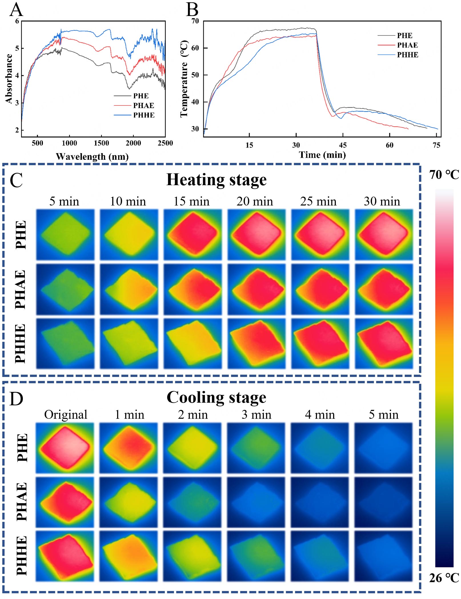
Figure 7. (A) UV-vis-NIR spectra of the CPCMs; (B) Surface temperature-time curves of the CPCMs; (C) infrared thermal images of the CPCMs during the heating stage; and (D) infrared thermal images of the CPCMs during the cooling stage. UV-vis-NIR: Ultraviolet-visible-near-infrared; CPCMs: composite phase change materials; PHE: PEG/HDI/EG; PHAE: PEG/HDI/APP/EG; PHHE: PEG/HDI/HAPP/EG; PEG: polyethylene glycol; HDI: hexamethylene diisocyanate; APP: ammonium polyphosphate; EG: expanded graphite; HAPP: hydroxylated ammonium polyphosphate.
Infrared thermal imaging was further employed to investigate the thermal response behavior of the samples during the light irradiation-cooling process. Figure 7B presents the surface temperature-time curves, while Figure 7C and D show the corresponding infrared thermal images. All three samples exhibited an obvious temperature increase under light irradiation and gradually reached a relatively stable temperature plateau. However, differences were observed in their heating rates, plateau temperatures, and temperature retention during cooling, reflecting distinct photothermal conversion, heat transfer, and thermal energy storage and release behaviors. During the heating stage, PHE showed a rapid temperature rise and maintained a relatively high plateau temperature. PHAE displayed a heating behavior similar to that of PHE, but with a slightly lower plateau temperature and poorer temperature stability. In contrast, PHHE exhibited a more gradual temperature increase in the early heating stage and subsequently approached the plateau temperature of PHE. Particularly within the phase transition temperature range, the heating rate of PHHE was markedly reduced, indicating that a larger fraction of the absorbed photothermal energy was stored as latent heat rather than being directly converted into surface temperature elevation, thereby producing a more pronounced thermal buffering effect. During the cooling stage, PHAE showed the fastest temperature decrease, suggesting relatively weak heat storage and delayed heat-release capabilities. Although PHE achieved a higher temperature during irradiation, its heat preservation ability was not outstanding. By comparison, PHHE exhibited a more evident temperature retention phenomenon and a slower cooling process within the phase transition region, demonstrating its ability to continuously release latent heat and prolong the temperature maintenance period. These results confirm that PHHE possesses superior thermal buffering and thermal regulation capability under practical photothermal cycling conditions.
To quantitatively evaluate photothermal energy storage, the apparent photothermal conversion efficiencies of the CPCMs were calculated using their respective sample masses, irradiated areas, melting enthalpies, and phase-transition durations. The phase-transition ranges of PHE, PHAE, and PHHE were 50.84-58.60, 53.04-58.49, and 50.00-59.53 °C, respectively, and the corresponding phase-transition durations were 211.01, 182.27, and 491.50 s. As summarized in Supplementary Table 5, the apparent photothermal conversion efficiencies of PHE, PHAE, and PHHE were calculated to be 71.47%, 73.04%, and 73.72%, respectively. The three CPCMs exhibited comparable efficiencies, with PHHE showing the highest calculated value under the present experimental conditions. Together with its strong broadband absorption and pronounced thermal-buffering behavior, this result supports the potential of PHHE for solar thermal energy storage.
Combined with the DSC results, the latent heats of PHE and PHHE were 115.21 and 111.35 J/g, respectively, indicating that PHE had a slightly higher phase change heat storage capacity per unit mass than PHHE. Nevertheless, PHHE still exhibited a more pronounced thermal buffering effect and more stable heat-release behavior in the photothermal response test. This suggests that the actual photothermal response of CPCMs is not solely determined by latent heat, but is also closely related to light absorption capacity, thermal conductivity, filler dispersion, and internal network structure. Notably, although PHHE showed the highest absorbance in the near-infrared region, its plateau temperature under irradiation was lower than that of PHE. This phenomenon can be attributed to the combined effects of latent heat storage and enhanced thermal conduction. On the one hand, PHHE can convert more absorbed heat into latent heat during the phase transition process, thereby suppressing the rapid increase in surface temperature. On the other hand, its higher thermal conductivity facilitates more uniform heat transfer and distribution within the material and promotes heat exchange with the surrounding environment, thus alleviating local heat accumulation. In contrast, although PHE has lower light absorbance than PHHE, its relatively weaker thermal conductivity causes absorbed heat to accumulate more readily on the surface or in localized regions, resulting in a higher plateau temperature. The key difference between PHHE and PHE lies in the introduction of the crosslinkable flame retardant HAPP, which not only imparts flame retardancy but also participates in the construction and regulation of the crosslinked network. The confinement effect of the crosslinked structure on the chain mobility of the phase-change component may slightly reduce the latent heat of PHHE, while the optimized network structure improves filler dispersion and heat-transfer pathways, promoting the synergistic interactions among light absorption, thermal conduction, and phase-change heat storage. In contrast, although PHAE contains the same mass fraction of flame-retardant component as PHHE, APP has a limited ability to regulate the network structure, making it difficult to simultaneously balance structural stability, thermal conduction, and phase change heat storage performance. Consequently, PHAE exhibits faster heating and cooling processes and weaker thermal regulation capability. Overall, the HAPP-induced crosslinked network can enhance broadband light absorption, thermal buffering, and heat-release stability while improving flame retardancy, demonstrating that rational design and regulation of the crosslinked network structure are essential for achieving the synergistic optimization of flame retardancy and phase change thermal energy storage performance.
Battery thermal management analysis
To evaluate the thermal-regulation performance of the CPCMs, three customized modules, namely the PHE-Module, PHAE-Module, and PHHE-Module, were assembled using the same module geometry, cell spacing, and thermocouple arrangement, as shown in Figure 8A-C and Supplementary Figure 5. Ten thermocouples, T1-T10, were used to monitor the cell surface temperatures. The detailed thermocouple arrangement and the calculation method for the maximum temperature difference are provided in the Supplementary Materials. Therefore, the comparison among the three modules mainly reflects the influence of the different CPCMs.
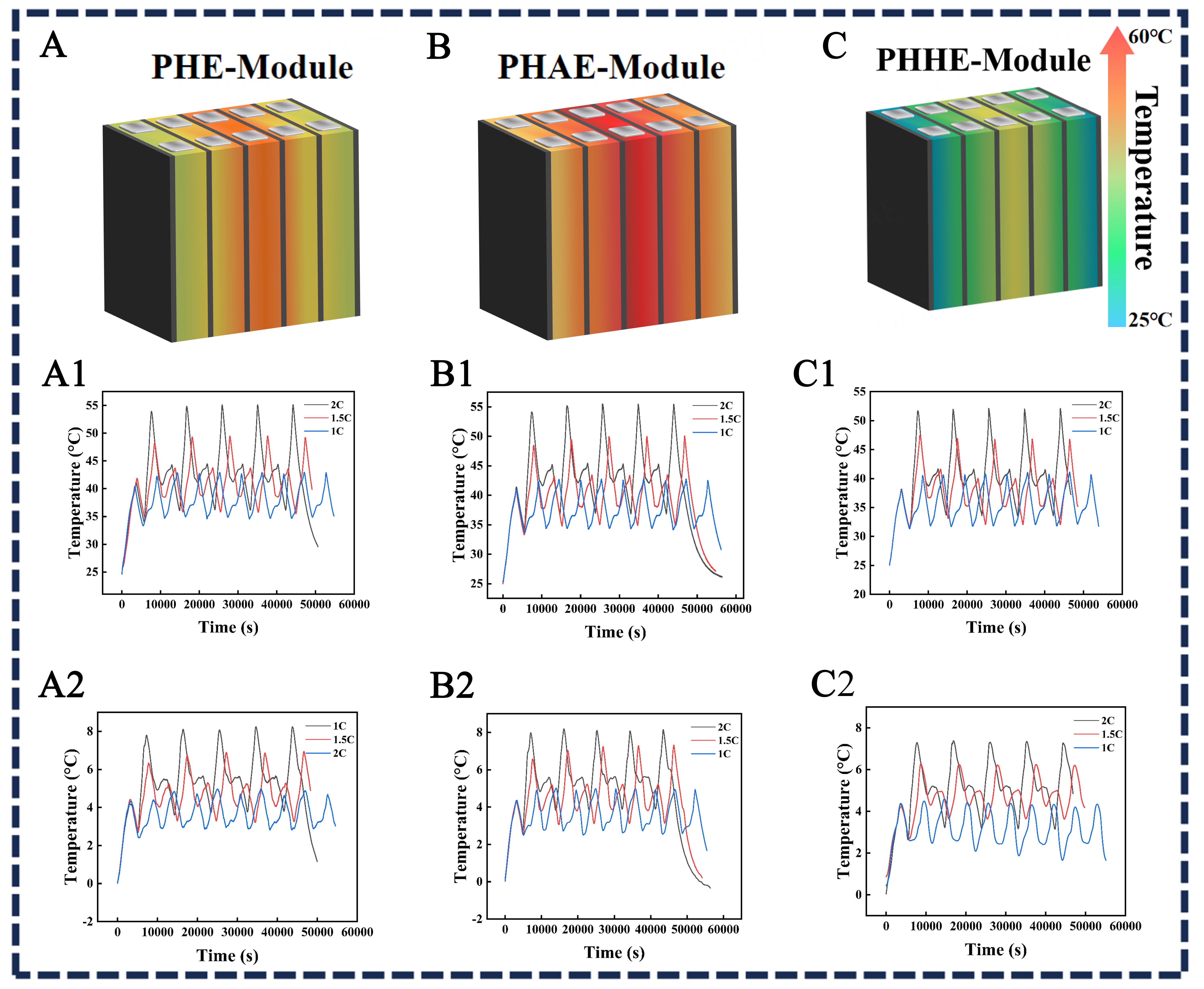
Figure 8. Thermal-management performance of battery modules containing different CPCMs: schematic configurations of (A) the PHE-Module, (B) the PHAE-Module, and (C) the PHHE-Module; maximum-temperature profiles during charge-discharge cycling of (A1) the PHE-Module, (B1) the PHAE-Module, and (C1) the PHHE-Module; maximum-temperature-difference profiles during charge-discharge cycling of (A2) the PHE-Module, (B2) the PHAE-Module, and (C2) the PHHE-Module. PHE: PEG/HDI/EG; PHAE: PEG/HDI/APP/EG; PHHE: PEG/HDI/HAPP/EG; CPCMs: composite phase change materials; PEG: polyethylene glycol; HDI: hexamethylene diisocyanate; APP: ammonium polyphosphate; EG: expanded graphite; HAPP: hydroxylated ammonium polyphosphate.
Figure 8A1-C1 and Figure 8A2-C2 present the maximum temperature and maximum temperature difference of the three modules during charge-discharge cycling at 1 C, 1.5 C, and 2 C. During the first cycle at 1 C, the maximum temperatures of the PHE-Module and PHAE-Module were 40.43 and 40.89 °C, respectively, whereas that of the PHHE-Module was 38.09 °C. As the discharge rate increased, the maximum temperature also increased. During the first cycle at 2 C, the maximum temperatures of the PHE-Module, PHAE-Module, and PHHE-Module were 53.78, 54.08, and 51.73 °C, respectively. The corresponding maximum temperature differences were 7.80, 7.98, and 7.30 °C, respectively.
The non-uniform temperature distribution is related to the module geometry, cell spacing, internal heat generation, and heat-transfer boundary conditions. Compared with cells located near the module edges, the central cells are surrounded by neighboring cells and have longer heat-dissipation paths, resulting in greater heat accumulation in the middle region. Cell spacing also affects thermal regulation. Smaller spacing increases module compactness but limits the amount of CPCM between adjacent cells, whereas larger spacing can accommodate more CPCM and improve thermal buffering at the expense of volumetric energy density. Therefore, cell spacing and CPCM thickness should be optimized together with the thermal conductivity and latent heat of the CPCM.
During continuous cycling at 2 C, progressive heat accumulation increased the module temperatures above those observed in the first cycle. The maximum temperatures of the PHE-Module and PHAE-Module reached 55.12 and 55.49 °C, respectively, whereas the PHHE-Module reached 52.08 °C. The corresponding maximum temperature differences were 8.19, 8.15, and 7.34 °C, respectively. Compared with the PHE-Module and PHAE-Module, the PHHE-Module reduced the maximum temperature by 3.04 and 3.41 °C, respectively. This moderate improvement is mainly attributed to the higher thermal conductivity of PHHE, which facilitates heat redistribution, together with its phase-change heat absorption and leakage-resistant solid-solid structure.
CONCLUSIONS
Efficient thermal management presents a critical challenge in both lithium-ion battery modules and solar energy systems, where temperature fluctuations can compromise energy conversion efficiency, storage stability, and operational safety. CPCMs have been extensively investigated as passive thermal management solutions. However, their large-scale application remains limited by insufficient thermal conductivity, low absorption in the solar spectrum, leakage, and flammability. Herein, multifunctional CPCMs with high latent heat, excellent anti-leakage performance, enhanced thermal conductivity, and flame-retardant properties are successfully fabricated. The main conclusions are summarized as follows:
(1) HAPP is synthesized via a cation-exchange reaction, and a CPCM is subsequently fabricated using HAPP, PEG, HDI, and EG. After treatment at 80 °C for 5 h, the material exhibits a mass retention exceeding 99.8%, with a latent heat of 111.35 J/g and a thermal conductivity of 1.547 W/(m·K). After 100 heating-cooling cycles, PHHE retained 99.30% of its initial melting enthalpy and 99.91% of its initial mass, demonstrating favorable thermal-cycling reliability and shape stability. Compared with PHE, PHHE shows a 14% increase in maximum absorbance, indicating improved solar light absorption.
(2) PHHE achieves a limiting oxygen index of 23.6%, considerably higher than that of PHE (21.1%). Cone calorimetry reveals a total heat release of 95.69 MJ/m2, with a peak smoke production rate of 0.069 m2/s and total smoke production of 10.68 m2, respectively. Compared with the APP-containing PHAE sample (PEG/HDI/APP/EG), incorporating HAPP reduces the peak smoke production rate from 0.097 to
(3) Under simulated solar irradiation, PHHE exhibits more pronounced temperature retention and a slower cooling process within the phase-transition range, indicating sustained latent heat release and prolonged temperature maintenance. At a discharge rate of 2 C, the PHHE-based battery module reaches a maximum temperature of 52.08 °C and a maximum temperature difference of 7.34 °C under the tested conditions. The relatively high thermal conductivity, solid-solid phase-transition behavior, and leakage resistance of PHHE contribute to heat absorption and transfer, thereby supporting passive thermal regulation in the solar-energy and battery-module tests.
Although PHHE demonstrates promising multifunctional performance, the present study is mainly based on laboratory-scale experiments under simulated solar irradiation and a limited battery-module configuration. Its long-term thermal cycling stability, mechanical durability, large-scale manufacturing feasibility, and performance under complex practical operating conditions require further investigation. Future work will focus on optimizing the material formulation and system configuration, evaluating long-term reliability, improving preparation scalability, and validating its thermal-management performance in larger battery packs and outdoor solar-energy systems.
Consequently, this research presents a potential material-design strategy for developing multifunctional CPCMs that integrate flame retardancy, thermal stability, and photothermal conversion capability, offering potential for future applications in solar thermal storage and battery thermal management.
DECLARATIONS
Authors’ contributions
Writing - original draft, investigation, formal analysis: He, R.
Writing - review and editing, methodology: Wu, X.; Li, X.; Li, C.
Investigation, methodology: Chen, P.
Investigation, data curation, validation: Shi, J.
Formal analysis, visualization: Xu, W.
Writing - review and editing, supervision, project administration, funding acquisition: Li, X.
Availability of data and materials
The raw data supporting the findings of this study are available within this Article and its Supplementary Materials. Further data are available from the corresponding authors upon request.
AI and AI-assisted tools statement
Not applicable.
Financial support and sponsorship
This research was financially supported by the Science and Technology Cooperation Program of Shanghai Jiao Tong University in Inner Mongolia Autonomous Region-Action Plan of Shanghai Jiao Tong University for “Revitalizing Inner Mongolia through Science and Technology” (2025XYJG0001-01-13) and the National Natural Science Foundation of China (52576198).
Conflicts of interest
Xu, W. is affiliated with Shenzhen DEM Technology Co., Ltd. The other authors declared that there are no conflicts of interest.
Ethical approval and consent to participate
Not applicable.
Consent for publication
Not applicable.
Copyright
© The Author(s) 2026.
Supplementary Materials
REFERENCES
1. Li, M.; Yin, T.; Wan, T.; et al. Unveiling the role of intermediate neutral hydrogen in bridging moisture-electric generation and hydrogen evolution. Adv. Mater. 2026, 38, e73176.
2. Zhang, M.; Xu, J.; Jiang, Y. Discovering technology convergence opportunities based on interactions between science and technology convergence: the case of artificial intelligence and renewable energy. Technol. Forecast. Soc. Change. 2026, 228, 124683.
3. Chowdhury, T.; Dehghanimadvar, M.; Chang, N. L.; Corkish, R. Evaluating short-circularity pathways for photovoltaic glass through life cycle assessment: cullet recycling versus whole-glass reuse. Sol. Energy. Mater. Sol. Cells. 2026, 300, 114227.
4. Zhang, K.; Zhou, Z.; Li, J.; et al. Circuit model-driven investigation of hot-spot behavior in n-type TBC photovoltaic modules. Sol. Energy. Mater. Sol. Cells. 2026, 299, 114179.
5. Liu, J.; Du, C.; Li, Z.; et al. Bioinspired thermo-actuated thermoelectric/phase-change system for all-day power generation. Adv. Compos. Hybrid. Mater. 2026, 9, 1592.
6. Tan, Y.; Zhang, X.; Lin, J.; Wang, Y. A perspective on photoelectrochemical storage materials for coupled solar batteries. Energy. Environ. Sci. 2023, 16, 2432-47.
7. Ayachi, S.; He, X.; Yoon, H. J. Solar thermoelectricity for power generation. Adv. Energy. Mater. 2023, 13, 2300937.
8. Liu, K.; Peng, Q.; Liu, Z.; Li, W.; Cui, N.; Zhang, C. Adaptive battery thermal management systems in unsteady thermal application contexts. J. Energy. Chem. 2024, 97, 650-68.
9. Hwang, F. S.; Confrey, T.; Reidy, C.; et al. Review of battery thermal management systems in electric vehicles. Renew. Sustain. Energy. Rev. 2024, 192, 114171.
10. Pan, X.; Ju, X.; Yuan, M.; Xu, C.; Du, X. Energy tracing of solar cells for spectral-beam-splitting photovoltaic/thermal (PVT) systems. Appl. Energy. 2023, 345, 121320.
11. Zhang, J.; Hu, Z.; Zheng, J.; et al. Photothermal-assisted solar hydrogen production: a review. Energy. Convers. Manag. 2024, 318, 118901.
12. Hu, D.; Huang, S.; Wen, Z.; Gu, X.; Lu, J. A review on thermal runaway warning technology for lithium-ion batteries. Renew. Sustain. Energy. Rev. 2024, 206, 114882.
13. Feng, X.; Zhang, F.; Huang, W.; Peng, Y.; Xu, C.; Ouyang, M. Mechanism of internal thermal runaway propagation in blade batteries. J. Energy. Chem. 2024, 89, 184-94.
14. Lei, Y.; Xu, L.; Chan, Q. N.; et al. Recent advances in separator design for lithium metal batteries without dendrite formation: implications for electric vehicles. eTransportation 2024, 20, 100330.
15. Wang, J.; Wang, S.; Yu, Y.; et al. Dual heat-absorbing inorganic flame-retardant composite phase change material for enhanced battery thermal safety. Chem. Eng. J. 2025, 519, 165205.
16. Yu, Z.; Zhang, J.; Pan, W. A review of battery thermal management systems about heat pipe and phase change materials. J. Energy. Storage. 2023, 62, 106827.
17. Li, W.; Nie, L.; Zhang, X.; Zhao, J. Research progress on hybrid battery thermal management systems based on phase change material. J. Energy. Storage. 2026, 141, 119179.
18. Li, T.; Pan, H.; Xu, L.; Ni, K.; Shen, Y.; Li, K. Shape-stabilized phase change material with high phase change enthalpy made of PEG compounded with lignin-based carbon. Int. J. Biol. Macromol. 2022, 213, 134-44.
19. Bharathiraja, R.; Ramkumar, T.; Selvakumar, M.; Radhika, N. Thermal characteristics enhancement of paraffin wax phase change material (PCM) for thermal storage applications. Renew. Energy. 2024, 222, 119986.
20. Guo, Y.; Hou, T.; Wang, J.; et al. Phase change materials meet microfluidic encapsulation. Adv. Sci. 2024, 11, e2304580.
21. Wang, T.; Yang, Y.; Wei, R.; et al. High-performance and anti-leakage polypyrrole-modified wood-based composite phase change material with superior photothermal conversion capability. J. Energy. Storage. 2025, 113, 115696.
22. Li, L.; Huang, Y.; Li, W.; et al. Regulation of thermal conductivity of microencapsulated phase change materials via atomic layer deposition. J. Energy. Storage. 2023, 68, 107668.
23. D'oliveira E, Azimov U, Costa Pereira S, Lafdi K. Effect of particle size on the thermal conductivity of organic phase change materials with expanded graphite. J. Energy. Storage. 2024, 92, 112090.
24. Yuan, Y.; Cheng, M.; Jing, H.; et al. In-situ cross-linking construction of gelatin based phase change aerogel toward advanced thermal energy conversion and storage. J. Energy. Storage. 2024, 93, 112423.
25. Liu, Y.; Gao, K.; Yi, H.; Xia, L.; Song, S. Flexible MoS2/CNF/PEG phase change film with superior photothermal conversion and thermal energy storage. Sol. Energy. Mater. Sol. Cells. 2025, 282, 113376.
26. Chen, Y.; Meng, Y.; Zhang, J.; et al. Leakage proof, flame-retardant, and electromagnetic shield wood morphology genetic composite phase change materials for solar thermal energy harvesting. NanoMicro. Lett. 2024, 16, 196.
27. Deng, X.; Li, C.; Sun, X.; et al. Flame-retardant wood-based composite phase change materials based on PDMS/expanded graphite coating for efficient solar-to-thermal energy storage. Appl. Energy. 2024, 368, 123454.
28. Wang, W.; Yang, X.; Fang, Y.; Ding, J. Preparation and performance of form-stable polyethylene glycol/silicon dioxide composites as solid-liquid phase change materials. Appl. Energy. 2009, 86, 170-4.
29. Ma, Y.; Zou, M.; Chen, W.; et al. A structured phase change material integrated by MXene/AgNWs modified dual-network and polyethylene glycol for energy storage and thermal management. Appl. Energy. 2023, 349, 121658.
30. Zhang, D.; Li, C.; Lin, N.; Xie, B.; Chen, J. Enhanced properties of mica-based composite phase change materials for thermal energy storage. J. Energy. Storage. 2021, 42, 103106.
31. Qiu, L.; Yan, K.; Feng, Y.; Liu, X. Nano additives-enhanced PEG/AlN composites with high cycle stability to improve thermal and heat storage properties. Energy 2023, 278, 127794.
32. Rajamony, R. K.; Kalidasan, B.; Chopra, K.; et al. Synergetic enhancement of thermal properties of phase change material using titanium carbide nanomaterial for enhanced thermal management in photovoltaic systems. Sol. Energy. Mater. Sol. Cells. 2026, 302, 114361.
33. Dong, L.; Wang, X.; Yu, X.; et al. Composite phase change materials made from cellulose that possess high energy storage capacity and outstanding photothermal conversion properties. Sol. Energy. Mater. Sol. Cells. 2025, 282, 113396.
34. Xu, D.; Huang, Q.; Yang, L.; et al. Experimental design of composite films with thermal management and electromagnetic shielding properties based on polyethylene glycol and MXene. Carbon 2023, 202, 1-12.
35. Gong, Y.; Zhang, J.; Chen, Y.; Ouyang, D.; Chen, M. Application of polyethylene glycol-based flame-retardant phase change materials in the thermal management of lithium-ion batteries. Polymers 2023, 15, 4450.
36. Wang, C.; Liu, P.; Liu, K.; Su, S.; Cheng, X.; Wang, Z. Study of the effect of layered structure on phase separation and heat transfer properties of phase change materials. J. Energy. Storage. 2024, 84, 110705.
37. Lee, S.; Park, S. Effects of superabsorbent polymer addition on the thermal properties of eutectic phase change material. Processes 2024, 12, 162.
38. Chen, Y.; Yang, M.; Song, Y.; et al. Leak-proof wood-based phase change materials composites utilizing chitosan encapsulation technology. J. Energy. Storage. 2025, 113, 115624.
39. Chen, R.; Yao, R.; Xia, W.; Zou, R. Electro/photo to heat conversion system based on polyurethane embedded graphite foam. Appl. Energy. 2015, 152, 183-8.
40. Shi, J.; Aftab, W.; Liang, Z.; et al. Tuning the flexibility and thermal storage capacity of solid-solid phase change materials towards wearable applications. J. Mater. Chem. A. 2020, 8, 20133-40.
41. Zhang, Y.; Wu, P.; Meng, Y.; Lu, R.; Zhang, S.; Tang, B. Flexible phase change films with enhanced thermal conductivity and low electrical conductivity for thermal management. Chem. Eng. J. 2023, 464, 142650.
42. Zhou, Y.; Wang, X.; Liu, X.; et al. Polyurethane-based solid-solid phase change materials with halloysite nanotubes-hybrid graphene aerogels for efficient light- and electro-thermal conversion and storage. Carbon 2019, 142, 558-66.
43. Bai, S.; Zhang, K.; Zhang, Q.; et al. Intrinsic flame retardancy and flexible solid-solid phase change materials with self-healing and recyclability. ACS. Appl. Mater. Interfaces. 2023, 15, 48613-22.
44. Mao, Y.; Li, J.; Yang, X.; et al. Heat transfer properties of graphene/polyethylene glycol composite phase change material modified by bifunctional titanate coupling agent. J. Energy. Storage. 2025, 116, 115803.
45. Zhang, P.; Fan, H.; Hu, K.; et al. Solvent-free two-component polyurethane conjugated with crosslinkable hydroxyl-functionalized ammonium polyphosphate: curing behaviors, flammability and mechanical properties. Prog. Org. Coat. 2018, 120, 88-99.
46. Su, Y.; Xu, X.; Chen, X.; et al. Experimental and numerical investigation of a battery thermal management system using a novel EVA-based thermal-induced flexible composite phase change material. J. Energy. Storage. 2024, 83, 110607.
47. Xing, M.; Jiao, Y.; Chen, H.; Ding, X.; Wang, Y. Optical and photo-thermal conversion characteristics of recyclable nano-ferrofluid under the external magnetic field. J. Clean. Prod. 2024, 434, 140212.
48. Duan, J.; Hou, Y.; Qian, X.; et al. Multilayer chitosan/silica-coated ammonium polyphosphate flame retardants for enhanced fire resistance of thermoplastic polyurethane. Constr. Build. Mater. 2025, 474, 141120.
49. Li, C.; Sun, Z.; Shao, J.; et al. A novel biochar supported dual-flame-retardant composite phase change material (PCM) for building energy saving. Constr. Build. Mater. 2025, 485, 141953.
50. Liu, A.; Gao, Z.; Cai, G.; et al. Preparation and characterization of expandable graphite/silicone resin co-modified polyurethane-based intumescent flame retardant thermal insulation coatings. Prog. Org. Coat. 2025, 205, 109316.
Cite This Article
 Open Access
How to Cite
Download Citation
Export Citation File:
Type of Import
Tips on Downloading Citation
Citation Manager File Format
Type of Import
Direct Import: When the Direct Import option is selected (the default state), a dialogue box will give you the option to Save or Open the downloaded citation data. Choosing Open will either launch your citation manager or give you a choice of applications with which to use the metadata. The Save option saves the file locally for later use.
Indirect Import: When the Indirect Import option is selected, the metadata is displayed and may be copied and pasted as needed.
About This Article
Copyright

Data & Comments
Data
0











Comments
Comments must be written in English. Spam, offensive content, impersonation, and private information will not be permitted. If any comment is reported and identified as inappropriate content by OAE staff, the comment will be removed without notice. If you have any queries or need any help, please contact us at support@oaepublish.com.