


Constructing an enhanced charge-mass transfer passage for silicon anodes to achieve increased capacity under high-rate conditions
 0
0 Abstract
Silicon (Si) holds promise as an anode material for next-generation lithium-ion batteries due to its high theoretical capacity. However, practical applications are impeded by structural damage from volume expansion. Here, we designed a novel Si/CNFs/C anode by integrating mesoporous Si particles, carbon nanofibers (CNFs), and carbon quantum dots into a three-dimensional (3D) architecture via a one-step magnesiothermic reduction process. This design significantly enhances both electron and ion conductivity, alleviates the volume expansion of Si particles, and ensures mechanical stability during battery operation. Consequently, batteries with the Si/CNFs/C anode exhibit a reversible capacity of 1,172.4 mAh g-1 after 200 cycles at 0.1 A g-1 and maintain 1,107.7 mAh g-1 after 1,000 cycles at 1 A g-1. Notably, after 1,000 cycles at a high current density of 1 A g-1, the capacity remains nearly comparable to that after 100 cycles at 0.1 A g-1, attributed to significant pseudocapacitive characteristics that facilitate high performance under elevated current densities. Furthermore, we employed distribution of relaxation times analysis alongside other electrochemical techniques to investigate changes in ion transport pathways and the evolving role of Si in the energy storage process. Our design and analysis provide valuable insights for optimizing 3D conductive architectures and understanding the dynamic electrochemical mechanisms of Si-based anodes, advancing the development of high-performance lithium-ion batteries.

Keywords
INTRODUCTION
The selection of anode material is fundamental to shaping the energy density, cycling stability, and overall electrochemical performance of lithium-ion batteries, as it directly governs key processes such as ion storage, charge transport, and structural integrity during cycling. Silicon (Si) has emerged as a leading candidate for next-generation lithium-ion battery anodes, attributed to its extraordinarily high theoretical capacity of 4,200 mAh g-1, low operating potential (~0.37 V vs. Li/Li+), and natural abundance, which collectively present immense potential for enhancing energy density[1]. Despite these advantages, its practical implementation is significantly constrained by a severe volume expansion (~400%) during lithiation and delithiation, resulting in structural pulverization, rapid capacity decay, and poor electrical conductivity that impedes efficient electron transport[2]. Overcoming these intrinsic challenges is critical to fully leveraging the benefits of Si and advancing the development of high-performance lithium-ion battery technologies[3].
To mitigate the challenges associated with Si anodes, integrating Si with carbon materials has emerged as an effective strategy[4-6]. Zhou et al. achieved a sustainable high-capacity Si anode by implementing a dual-layer interface architecture that integrates an internal SiOx layer with an external N, B co-doped carbon coating, accommodating the volumetric changes of Si during cycling and establishing robust pathways for ion and electron transport, thereby significantly enhancing the stability and electrochemical performance of the anode[7]. Similarly, Han et al. enhanced electrical conductivity and mitigated stress by designing a hierarchical submicron Si-carbon architecture that incorporates nanoscale Si particles within a conductive carbon matrix, thereby establishing resilient conductive networks and effectively accommodating the volumetric expansion of Si during charge-discharge cycles[8]. Collectively, these studies have significantly improved cycling stability and rate performance, thereby advancing the development of Si anodes.
Despite these encouraging advances, Si-based anodes still face fundamental hurdles, including disrupted conduction pathways and sluggish electrochemical kinetics, which lead to uneven lithium-ion distribution, heightened polarization, and ultimately diminished rate capability[9,10]. An optimized structural design is therefore essential to fully harness the high theoretical capacity of Si. Specifically, three key elements are crucial: (i) structural modification of Si to introduce ion diffusion channels and address slow kinetics, (ii) incorporation of conductive networks to enhance electron transport and suppress volume expansion, and (iii) design of mass transport pathways to enable efficient ion and electron movement from external carbon to the interior of Si[11-15]. Guided by these principles, our approach introduces ion diffusion channels, robust conductive frameworks, and optimized mass transport routes to collectively improve electrochemical performance and extend the operational lifespan of anodes.
Building on this framework, the present study proposes a novel structural optimization by developing a
EXPERIMENTAL
Synthesis of samples
Materials
All reagents and chemicals were obtained from Shanghai Macklin Biochemical Co., Ltd. (Shanghai, China) and used as received, without any further purification.
Synthesis of carbon quantum dots
CQDs were synthesized using a microwave-assisted method. Initially, 5 g of citric acid and 5 g of urea were thoroughly dissolved in 20 mL of deionized water with continuous stirring to form a uniform solution. This homogeneous mixture was then subjected to microwave heating at a power level of 1,100 W for 5 min using a standard household microwave oven. After microwave irradiation, the mixture was allowed to cool to room temperature, resulting in the formation of a black solid residue. This solid was collected and
Synthesis of carbon nanofibers
CNFs were synthesized via electrospinning, followed by thermal stabilization and carbonization. Polyacrylonitrile (PAN) (1 g) was dissolved in 10 mL of N, N-dimethylformamide (DMF) and stirred at room temperature for 24 h to achieve complete dissolution. The solution was then sonicated for 30 min to remove any air bubbles. The PAN solution was loaded into a syringe fitted with a flat-head needle and electrospun under controlled conditions to form uniform nanofibers. The collected nanofibers were vacuum-dried at 60 °C for 6 h to eliminate the residual solvent. The dried mats were then thermally stabilized at 260 °C for 3 h in the air to induce cyclization and aromatization. Finally, the stabilized fibers were carbonized in an argon atmosphere at 800 °C, with a heating rate of 2 °C min-1, for 2 h to yield CNFs.
Synthesis of Si/CNFs/C, Si/CNFs, and Si/C composites
The Si/CNFs/C, Si/CNFs, and Si/C composites were prepared via magnesiothermic reduction of SiO2 nanoparticles, as detailed in our previous publication[13]. For the synthesis of Si/CNFs/C, a mixture of 0.6 g of SiO2, 0.1 g of CQDs, 0.1 g of CNFs, and 0.6 g of NaCl was ground in an agate mortar until homogeneous. In this process, NaCl acted as both a dispersing agent to prevent particle agglomeration and a thermal conductor to promote uniform heat distribution during the reduction. The mixture was then blended with 0.6 g of magnesium powder, which served as the reducing agent. The resulting blend was placed in a tube furnace and subjected to magnesiothermic reduction at 650 °C for 6 h under an argon atmosphere to prevent oxidation. After cooling to room temperature, the product was washed sequentially with 1 mol L-1 hydrochloric acid (HCl) and 4% hydrofluoric acid (HF) to remove residual magnesium, MgO, Mg2Si, and unreacted SiO2. The sample was then rinsed with deionized water until the pH reached neutral. To eliminate residual moisture, the product was vacuum-dried at 60 °C for 12 h. For comparison, Si/CNFs and Si/C composites were synthesized under identical conditions, excluding the addition of CQDs and CNFs, respectively, to assess the individual contributions of these components to the composite properties.
Characterization
The phase composition and crystal structure of the synthesized samples were examined using X-ray diffraction (XRD) on a LabRAM HR800 diffractometer with Cu Kα radiation (λ = 0.15418 nm). The scans were conducted over a 2θ range of 20° to 70° with a step size of 0.02° and a scan rate of 6° min-1, providing detailed information on the crystalline phases. The surface morphology and microstructure were characterized by scanning electron microscopy (SEM, Zeiss Gemini 500) and transmission electron microscopy (TEM, JEM-F200). Elemental composition and distribution were further analyzed using
Electrochemical measurement
The working anodes were prepared by mixing the active material, conductive carbon black (Super P), and sodium carboxymethyl cellulose (CMC) binder in a 7:2:1 mass ratio using deionized water to form a uniform slurry. The slurry was coated onto copper foil and dried at 80 °C for 12 h to eliminate residual moisture, achieving active material mass loadings of 0.76 mg cm-2 for Si/CNFs/C, 0.648 mg cm-2 for
Calculation method
Spin-polarized density functional theory (DFT) calculations were performed using plane-wave basis sets and the projector augmented-wave (PAW) method. The exchange-correlation functional was treated using the generalized gradient approximation (GGA) with the Perdew-Burke-Ernzerhof (PBE) parameterization. An energy cutoff of 400 eV was set for the calculations. The Brillouin-zone integration was carried out using a Γ-centered Monkhorst-Pack grid of
RESULT AND DISCUSSION
To address the inherent challenges of Si anodes, including poor conductivity and significant volumetric expansion during cycling, we designed a novel strategy based on a one-step magnesiothermic reduction process [Scheme 1]. This approach enabled the successful fabrication of a Si/CNFs/C composite with 3D conductive pathways, exhibiting exceptional electrochemical performance. The method effectively addresses the key limitations of Si, providing a robust solution for improving cycling stability and rate capability[16].

Scheme 1. Schematic illustration of the one-step magnesiothermic reduction process for synthesizing the Si/CNFs/C composite. CNFs: Carbon nanofibers; CQDs-C: carbon quantum-derived carbon.
In this synthesis, the Si particles inherit the mesoporous structure of the dendritic SiO2 precursor, which plays a vital role in forming internal ion diffusion channels. These channels effectively reduce ion transport resistance, a common challenge in traditional Si-based anodes, thereby significantly enhancing the anode’s electrochemical kinetics[17]. The SEM image of the SiO2 precursor [Figure 1A] reveals a well-defined dendritic mesoporous structure, offering a highly accessible porous framework essential for facilitating efficient ion diffusion. Additionally, the inset TEM image confirms the presence of continuous internal pores extending from the interior to the surface. During the magnesiothermic reduction process, this porous architecture is preserved in the Si particles, further improving ion transport and enhancing electrochemical performance[18]. Figure 1B-C shows SEM images of the synthesized Si/CNFs/C composite, which features a network-like morphology with interwoven CNFs forming a 3D porous architecture. Employing NaCl as a pore-forming agent effectively fosters the formation of this porous architecture while preventing particle agglomeration[19]. For comparison, Si/CNFs and Si/C anodes were also prepared using similar methods, as illustrated in Supplementary Figure 1. The small size of the CQDs allows them to penetrate into the mesoporous Si structures, generating carbon layers in situ on the inner walls of the Si pores [Figure 1D]. This process leads to the formation of an interpenetrating 3D conductive network that connects the external carbon matrix to the internal Si particles, which is critical for facilitating both ion diffusion and electron transport, thereby enhancing electrochemical kinetics[20,21]. The two-dimensional carbon layers derived from CQDs and the one-dimensional CNFs form a robust, interconnected conductive network that promotes electron transport and maintains structural integrity. This hierarchical structure of the composite is demonstrated in the TEM image [Figure 1E], which shows the interconnection of the carbon layers and CNFs. The selected area electron diffraction (SAED) pattern [Figure 1F] further confirms the crystalline nature of the Si phase by exhibiting distinct diffraction rings characteristic of crystalline Si, supporting the successful reduction of SiO2 to Si. The high-resolution TEM (HRTEM) image [Figure 1G] displays clear lattice fringes with a spacing of 0.31 nm, corresponding to the (111) crystal plane of crystalline Si, further confirming the crystalline nature of Si in the composite and verifying the successful transformation of SiO2 to Si. Elemental mapping images [Figure 1H] demonstrate the homogeneous distribution of Si and carbon within the composite. The Si particles are uniformly embedded within the carbon matrix, with CNFs interwoven throughout the network. Together, the CNFs and CQDs-C form a continuous 3D structure that encapsulates the Si particles, enhancing electron transport and providing mechanical support to the composite, thereby greatly improving its electrochemical performance.

Figure 1. (A) SEM image of the SiO2 precursor; inset: TEM image of SiO2; Morphology and compositional analysis of the Si/CNFs/C composite: (B and C) SEM images at low and high magnifications; (D and E) TEM images at varying magnifications; (F) Selected area electron diffraction (SAED) pattern; (G) High-resolution TEM (HRTEM) image; (H) Elemental mapping. SEM: Scanning electron microscopy; TEM: transmission electron microscopy.
XRD analysis, as shown in Figure 2A, was performed to explore the structural properties of the synthesized materials. After magnesiothermic reduction and subsequent HF washing to remove residual by-products, distinct diffraction peaks at 28.4°, 47.3°, 56.1°, and 69.1° were observed, corresponding to the (111), (220), (311), and (400) planes of crystalline Si (JCPDS No. 27-1402), indicating that the SiO2 in the composite was effectively reduced to Si[13]. To further investigate the composition and thermal stability of the samples, TGA was conducted, and the results are presented in Figure 2B. The TGA curves show three distinct stages, representing the evaporation of residual water, the oxidation of Si, and the combustion of carbon, respectively[22]. Based on the TGA data, the Si content in the Si/C, Si/CNFs, and Si/CNFs/C composites was determined to be 72.9%, 76.8%, and 63.2%, respectively. To assess the porosity and surface area of the

Figure 2. (A) XRD patterns of Si/C, Si/CNFs, and Si/CNFs/C composites; (B) TGA curves of Si/C, Si/CNFs, and Si/CNFs/C composites; (C) N2 adsorption-desorption isotherms of the Si/CNFs/C composite; (D) Raman spectra of Si/C, Si/CNFs and Si/CNFs/C composites; (E) C 1s and (F) Si 2p XPS spectrum of the Si/CNFs/C. CNFs: Carbon nanofibers; XRD: X-ray diffraction; TGA: thermogravimetric analysis; XPS: X-ray photoelectron spectroscopy.
To evaluate the electrochemical behavior of Si/C, Si/CNFs, and Si/CNFs/C composite anodes, CV tests were performed at a scan rate of 0.5 mV s-1, as illustrated in Figure 3A. For the Si/CNFs/C composite, three reduction peaks appear in the first cathodic sweep, located around 1.42 V, 0.26 V, and 0.12 V. These peaks are attributed to Li+ storage within the carbon matrix, the formation of the solid electrolyte interphase (SEI), and the subsequent alloying reaction producing LixSi phases, respectively. During the anodic sweep, a distinct peak emerges at approximately 1.24 V, corresponding to the extraction of Li+ ions from the carbon matrix. In subsequent cycles, the redox behavior stabilizes, exhibiting a reduction peak at ~0.85 V and an oxidation peak near 1.24 V, indicating the reversible insertion/extraction of Li+. For comparison, the CV curves of Si/C and Si/CNFs anodes are provided in Supplementary Figure 3, respectively. The Si/C and

Figure 3. (A) CV curves of the Si/CNFs/C anode during the first three cycles; (B) Cycling performance of Si/C, Si/CNFs, and Si/CNFs/C anodes; (C) Rate capability of the three anodes; (D) GCD profiles of the Si/CNFs/C anode at different current densities; (E) GITT curves of Si/C, Si/CNFs, and Si/CNFs/C anodes; (F) Calculated lithium-ion diffusion coefficients for Si/C, Si/CNFs, and Si/CNFs/C anodes; (G) Nyquist plots of fresh Si/C, Si/CNFs, and Si/CNFs/C anodes; (H) Pseudocapacitive contribution of the Si/CNFs/C anode at a scan rate of 0.6 mV s-1; (I) Pseudocapacitive contributions of the Si/CNFs/C anode at various scan rates. CV: Cyclic voltammetry; CNFs: carbon nanofibers; GCD: galvanostatic charge-discharge; GITT: galvanostatic intermittent titration technique.
Figure 3C demonstrates the rate performance of the Si/C, Si/CNFs, and Si/CNFs/C anodes over a range of current densities (0.1 A g-1 to 5 A g-1). The Si/CNFs/C anode exhibits exceptional rate capability, delivering specific capacities of 1,062.2 mAh g-1, 1,013.3 mAh g-1, 870.6 mAh g-1, 788.6 mAh g-1, and 698.8 mAh g-1 at current densities of 0.1 A g-1, 0.2 A g-1, 0.5 A g-1, 1 A g-1, and 2 A g-1, respectively. Even at a high current density of 5 A g-1, it maintains a notable capacity of 582 mAh g-1. When the current density is reduced back to 0.1 A g-1, the capacity quickly recovers to 1,191.3 mAh g-1, which is nearly identical to the second cycle’s value at the same current density. The GCD profiles of the Si/CNFs/C anode at various current densities, presented in Figure 3D, indicate minimal capacity decay with increasing current density from 0.1 A g-1 to
To analyze the exceptional electrochemical performance of the Si/CNFs/C composite from the perspective of reaction kinetics, GITT measurements were carried out on all three anodes, as shown in Figure 3E. The lithium-ion diffusion behavior was evaluated using the logarithmic form of the diffusion coefficient (log D), which can be derived from
where L is the diffusion length of the lithium ion, ∆Es is the steady-state voltage change after removing the current pulse, ∆Eτ is the voltage change during the current pulse (excluding the IR drop), and τ is the duration of the current pulse[23]. A larger value of log D indicates a faster lithium-ion diffusion rate within the material. Figure 3F presents the lithium-ion diffusion rates in the anodes. Evidently, the average log D for the Si/CNFs/C anode is -12.672, significantly higher than that of the Si/CNFs anode (-12.829) and the
High-rate performance in lithium-ion batteries is enabled by anodes with significant pseudocapacitive contributions, reduced lithium-ion diffusion pathways, and efficient mass transport kinetics[27]. To probe the origin of the superior rate capability of the Si/CNFs/C anode, CV tests were performed at various scan rates (0.2 mV s-1, 0.4 mV s-1, 0.6 mV s-1, 0.8 mV s-1, and 1.0 mV s-1) for all anodes, as shown in Supplementary Figure 5, to quantify their pseudocapacitive behavior[28]. The pseudocapacitive and diffusion-controlled contributions were separated using
where i represents the peak current, v indicates the scan rate, and k1 and k2 correspond to the
To evaluate the long-term cycling stability of the three anodes, ultra-long cycling tests were conducted at a current density of 1 A g-1, as depicted in Figure 4A. During the early cycles, all anodes experienced a slight capacity reduction, attributed to the initial lithiation of Si and minor structural volume changes. After 1,000 cycles, the Si/CNFs/C anode exhibited an impressive reversible capacity of 1,107.7 mAh g-1, which is over three times higher than that of the Si/CNFs anode (365.3 mAh g-1) and more than twice that of the Si/C anode (513 mAh g-1). A comparative analysis of the cycling performance, shown in Figure 4B, reveals that the Si/CNFs/C anode outperforms a wide range of previously reported Si-based materials, demonstrating its exceptional stability and robust capacity retention over extended cycling.
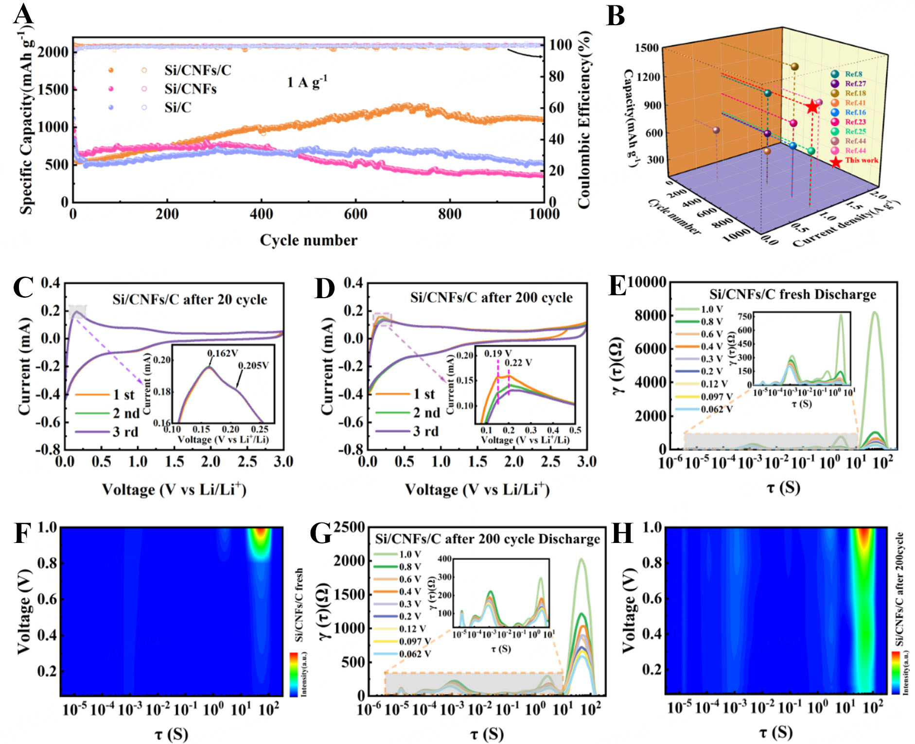
Figure 4. (A) Long-term cycling performance of Si/C, Si/CNFs, and Si/CNFs/C anodes at 1,000 mA g-1; (B) Comparative analysis of cycling performance with previously reported studies. (C and D) CV curves of the Si/CNFs/C anode recorded after 20 and 200 cycles, respectively; (E-H) DRT curves and corresponding transformations of in-situ EIS spectra for the Si/CNFs/C anode in its fresh state and after 200 cycles of operation. CNFs: Carbon nanofibers; CV: cyclic voltammetry; DRT: distribution of relaxation times; EIS: electrochemical impedance spectroscopy.
Building upon the impressive long-term cycling performance of the Si/CNFs/C anode, we observed a particularly intriguing phenomenon: the anode’s capacity not only stabilized but actually increased during prolonged cycling. Specifically, during the 200-cycle test at a current density of 0.1 A g-1, the capacity of the Si/CNFs/C anode initially exhibited a slight decline but then began to increase steadily over subsequent cycles. This upward trend in capacity was evident across various current densities during the rate performance tests, and it became even more pronounced when the current density was returned to
To gain deeper insights into the intriguing capacity increase observed in the Si/CNFs/C anode during prolonged cycling, we conducted EIS measurements after different numbers of cycles, as illustrated in Supplementary Figure 7. The Nyquist plots exhibit two distinct semicircles in the medium-to-high frequency range and a straight line in the low-frequency region, offering insights into the anode’s electrochemical behavior, with corresponding kinetic parameters detailed in Supplementary Table 1. The semicircle near the high-frequency region corresponds to the resistance of the SEI (RSEI), while the second semicircle, located in the medium-frequency region, represents the Rct[27]. As shown in Supplementary Figure 7B, after three cycles, the relatively high RSEI suggests that the SEI layer is still forming and not yet fully stabilized, thereby hindering lithium-ion transport[31]. As cycling progresses to 50 cycles, we observe that RSEI slightly decreases compared to the value after three cycles; this observed reduction in RSEI suggests that the SEI layer is becoming more stable, with a more uniform chemical composition and physical structure, thus facilitating smoother lithium-ion passage[32]. However, at 100 cycles, RSEI increases significantly to 16.7 Ω. This rise in resistance indicates changes occurring within the SEI layer; we interpret this increase as evidence that newly activated Si particles are beginning to participate in lithiation reactions, leading to uneven SEI growth or inhomogeneous reactions on the anode surface, which temporarily increase resistance[33]. By comparing RSEI values at different cycles, we deduce that the state of the SEI layer is changing due to the activation of Si particles[34]. By 200 cycles, RSEI dramatically decreases to 6.1 Ω, even lower than after 50 cycles. This significant reduction in RSEI suggests that the chemical composition and structure of the SEI layer have further stabilized, enhancing lithium-ion transport within the anode and reducing resistance[35]. Similarly, the medium-frequency semicircle representing Rct undergoes analogous transformations. After 50 cycles, Rct decreases markedly compared to after three cycles, indicating improved conductive pathways and enhanced electron transfer kinetics; this suggests that the conductive network within the composite has become more efficient, facilitating charge transfer[36]. As cycling continues to 100 cycles, Rct increases, which we interpret as resulting from newly activated mesoporous Si particles that have not yet established effective conductive pathways with the carbon matrix and the external electrolyte. By comparing Rct data at different cycles, we deduce that the state of the conductive pathways is evolving[37]. By 200 cycles, Rct diminishes again as these Si particles form robust connections with the carbon matrix and electrolyte, enhancing charge transfer[38]. To further substantiate these findings, we analyzed the Warburg coefficient (σ), derived from the relationship between the real part of the impedance (Z’) and the inverse square root of angular frequency (ω-1/2), as depicted in Supplementary Figure 7C. The σ is inversely proportional to the DLi+; the trend of DLi+ mirrors the changes observed in RSEI and Rct, indicating that the activation and structural reconfiguration processes intricately affect not only the Si particles and conductive pathways but also the lithium-ion transport routes[23]. By comparing data at different cycles, we conclude that lithium-ion diffusion is influenced by these evolving processes. Collectively, these interwoven observations depict a dynamic system where continuous activation of Si particles drives structural evolution. Using the impedance data at different cycling stages, we infer that initially, the activation introduces transient impedances, but over time, the system reorganizes into a more efficient architecture. This progression leads to stabilized SEI layers, re-establishes conductive networks, and enhances
To gain deeper insights into the internal electrochemical processes occurring within the Si/CNFs/C anode during cycling, we employed the in-situ DRT technique. We chose DRT because it allows us to decompose the impedance spectra into individual electrochemical processes without relying on equivalent circuit models, thereby providing an unbiased and detailed assessment of the anode’s dynamic behavior[39]. This approach not only avoids the potential pitfall of using results to prove results but also offers a deeper understanding of the mechanisms at play, directly connecting this analysis with our earlier observations of capacity enhancement and impedance changes. In the DRT spectra, as shown in Figure 4E-H and Supplementary Figure 8, three distinct peaks are identified, each corresponding to specific time intervals associated with different electrochemical processes: Peak (i) with time constants greater than 10 s (RD: Diffusion Resistance) represents the diffusion of Li+ ions within the bulk of the anode material (bulk diffusion), indicating the impedance associated with Li+ ions penetrating into the material; Peak (ii) with time constants between 10-4 s and 10 s (Rct) corresponds to the Rct between the material surface and the bulk, reflecting the kinetics of electrochemical reactions at the anode/electrolyte interface; and Peak (iii) with time constants less than 10-4 s (RSEI) is associated with interfacial reactions at the SEI layer, representing the impedance encountered by lithium ions traversing the SEI layer[40]. As for DRT results, more approximate time constants for different DRT peaks of the fresh Si/CNFs/C anode and after 200 cycles are provided in Supplementary Tables 2 and 3, respectively[41]. By comparing the fresh anode with the one after 200 cycles, we observed that the RD and Rct values in the cycled anode are significantly lower. This reduction indicates that after prolonged cycling, the Si/CNFs/C anode exhibits faster electron and ion transport due to the activation of Si particles and the establishment of efficient conductive networks. Notably, the reduction in
The structural evolution of Si/C, Si/CNFs, and Si/CNFs/C anodes after 1,000 cycles was investigated via SEM, as shown in Figure 5A-F, providing critical insights into the volume changes of these composite Si anodes. Initially, the anode thicknesses were measured to be 8.5 μm, 11.2 μm, and 11.1 μm for Si/CNFs/C, Si/CNFs, and Si/C, respectively. After 1,000 cycles, these values increased to 10 μm, 25.2 μm, and 14.1 μm, corresponding to expansions of 17.6%, 123.2%, and 27.2%, respectively. Notably, the Si/CNFs/C anode demonstrated the lowest volume expansion, a testament to its robust and innovative structural design. The CQDs-C forms a conformal coating around Si particles, effectively restraining their volumetric expansion during repeated lithiation and delithiation cycles[42]. Simultaneously, CNFs function as a mechanically resilient framework, accommodating the stress induced by the inherent volume changes of Si and maintaining the structural integrity of the electrode during prolonged cycling[43].

Figure 5. Cross-sectional images of anodes before cycling: (A) Si/CNFs/C, (B) Si/CNFs, (C) Si/C. After 1,000 cycles: (D) Si/CNFs/C, (E) Si/CNFs; (F) Si/C; (G) Schematic of ion and electron transport pathways in the composite structure. CNFs: Carbon nanofibers.
Beyond mechanical stability, the 3D architecture of the Si/CNFs/C anode delivers substantial enhancements in both electron and lithium-ion transport, as illustrated in Figure 5G. The interconnected CNF network ensures efficient electron conduction, enabling uniform charge distribution throughout the anode. Concurrently, the in-situ carbon layers derived from CQDs-C not only immobilize the Si particles but also establish well-dispersed ion diffusion pathways, fostering uniform and rapid lithium-ion transport. These synergistic effects mitigate lithium-ion concentration polarization, alleviate localized stress, and promote uniform lithiation and delithiation processes. This unique structural configuration effectively reduces internal resistance, supports high-rate capability, and enhances cycling stability.
To gain a deeper understanding of the fundamental reasons behind the improvement afforded by carbon coating on Si-based materials, we performed DFT calculations on Si/CNFs/C[44]. As illustrated in Supplementary Figure 9, in the Si/CNFs/C model, the blue spherical structures represent the crystalline Si substrate, while the red spheres denote oxygen atoms. The combination of Si and oxygen atoms indicates the small amount of SiO2 formed by surface oxidation of Si, as revealed by the XPS analysis. The brown layer on top is the carbon coating, which consists of amorphous carbon derived from CNFs and CQDs-C. Figure 6A shows the differential charge density distribution at the Si(111)/C(001) interface, illustrating how charges are redistributed at this interface and providing crucial information on the interaction between the Si(111) and C(001) surfaces. First, the differential charge density in the Si(111) region is close to zero, indicating that the charge distribution on the Si surface remains relatively stable. However, in the C(001) region, the differential charge density undergoes a pronounced change, particularly at the interface (~15 Å). The sharp peaks observed in this area reveal significant charge accumulation or depletion. This phenomenon can be attributed to the electronic interaction between the two materials, where the carbon layer draws electrons from the Si surface, causing a marked change in the surface charge density of carbon. Such electron transfer implies a strong electronic coupling effect at the Si/CNFs/C interface, exerting a significant influence on the electronic states of the Si surface[45]. The change in charge density directly reflects the interfacial interaction of these materials, further demonstrating that the Si layer can effectively modify the electronic structure of the Si surface through electron transfer, potentially impacting the interface’s conductivity, stability, and electrochemical performance. Figure 6B presents the planar-averaged potential distribution of the Si/CNFs/C sample along the distance axis, with dashed lines marking key energy levels, including the Fermi level (EF) and the vacuum level (Evac). From these calculations, the work function (WF) is found to be 4.82 eV, representing the minimum energy required for electrons to escape from the material’s surface. The WF is closely tied to the surface structure of the material[46]. In the

Figure 6. (A) One-dimensional difference charge density profile along the interface; (B) Work Function of the Composite Interface; (C) Top view of the three-dimensional difference charge density isosurface; (D) Side view of the three-dimensional difference charge density isosurface. WF: Work function.
Figure 6C and D provides a detailed view of the differential charge density distribution at the Si and C interface, represented using isosurface plots with color gradients distinguishing regions of charge accumulation and depletion. The yellow regions indicate charge accumulation, while the cyan-blue regions represent charge depletion. It is clearly observed that a large yellow cloud is present on the side near the carbon layer, while a distinct cyan-blue region is observed in the adjacent area of the Si surface. This indicates significant electron transfer at the interface, where electrons flow from the Si substrate to the carbon layer. This electron coupling at the interface is the essential mechanism through which carbon coating improves the performance of Si-based materials. First, the migration of electrons from the Si surface to the carbon layer effectively passivates the Si surface states, reducing the interface defect density and minimizing the likelihood of side reactions. In lithium-ion batteries, this passivation can significantly enhance the chemical stability and cycling life of the material. Second, the conductive network formed by the carbon layer enhances the efficiency of electron transport, making the charge distribution at the interface more balanced and reducing interface impedance, which is particularly critical for achieving
CONCLUSIONS
In this study, we have successfully designed and synthesized a 3D Si/CNFs/C anode. The innovative architecture enhances electron and ion transport, mitigates the volume expansion of Si during cycling, and ensures mechanical stability. Consequently, the Si/CNFs/C anode has delivered excellent electrochemical performance, achieving a reversible capacity of 1,172.4 mAh g-1 after 200 cycles at 0.1 A g-1 and maintaining 1,107.7 mAh g-1 after 1,000 cycles at 1 A g-1. Notably, a unique capacity increase phenomenon has been observed during prolonged cycling, which has been attributed to the progressive activation of Si particles deeply embedded within the composite matrix. We revealed that this activation process is accompanied by dynamic structural and electrochemical adjustments, including the formation of efficient conductive pathways and stabilized SEI layers. These findings underscore the self-improving behaviors of the
DECLARATIONS
Authors’ contributions
Writing - original draft, methodology, investigation, conceptualization: Liu, J.
Writing - original draft, investigation, formal analysis: Wan, Y.
Investigation: Wang, K.; Wang, K.
Writing - review and editing, formal analysis: Sun, W.
Investigation, conceptualization: Dai, J.
Investigation, formal analysis: Li, Z.
Writing - review and editing, investigation, formal analysis: Ran, F.
Availability of data and materials
The data supporting the findings of this study are available within this Article and its Supplementary Materials. Further data are available from the corresponding authors upon request.
Financial support and sponsorship
This work was financially supported by the National Natural Science Foundation of China (22369009), the Gansu Provincial Youth Science and Technology Fund Projects (23JRRA865, 24JRRA989), the Science and Technology Plan Project of Jinchang (2024GY004), the Natural Science and Technology Development Guidance Plan Fund Project of Lanzhou (2022-ZD-149), the Gansu Provincial Natural Science Foundation Project (24JRRF006), the Gansu Provincial Youth Talent Team Project (2024QNTD38), the Jiuquan Science and Technology Support Plan Project (2023CA2057), the Gansu Provincial University Teachers Innovation Fund Project (2025A-043), and the Tianyou Youth Talent Lift Program of Lanzhou Jiaotong University.
Conflicts of interest
All authors declared that there are no conflicts of interest.
Ethical approval and consent to participate
Not applicable.
Consent for publication
Not applicable.
Copyright
© The Author(s) 2025.
Supplementary Materials
REFERENCES
1. He, Z.; Zhang, C.; Zhu, Y.; Wei, F. The acupuncture effect of carbon nanotubes induced by the volume expansion of silicon-based anodes. Energy. Environ. Sci. 2024, 17, 3358-64.
2. Liu, J.; Huang, L.; Wang, H.; et al. The origin, characterization, and precise design and regulation of diverse hard carbon structures for targeted applications in lithium-/sodium-/potassium-ion batteries. Electrochem. Energy. Rev. 2024, 7, 34.
3. Zhang, P.; Wang, X.; Zhang, Y.; et al. Burgeoning silicon/MXene nanocomposites for lithium ion batteries: a review. Adv. Funct. Mater. 2024, 34, 2402307.
4. He, Z.; Zhang, C.; Zhu, Z.; Yu, Y.; Zheng, C.; Wei, F. Advances in carbon nanotubes and carbon coatings as conductive networks in silicon-based anodes. Adv. Funct. Mater. 2024, 34, 2408285.
5. Wang, L.; Han, J.; Kong, D.; Tao, Y.; Yang, Q. H. Enhanced roles of carbon architectures in high-performance lithium-ion batteries. Nano-Micro. Lett. 2019, 11, 5.
6. Yan, W.; Mu, Z.; Wang, Z.; et al. Hard-carbon-stabilized Li-Si anodes for high-performance all-solid-state Li-ion batteries. Nat. Energy. 2023, 8, 800-13.
7. Zhou, J.; Lu, Y.; Yang, L.; et al. Sustainable silicon anodes facilitated via a double-layer interface engineering: inner SiOx combined with outer nitrogen and boron co-doped carbon. Carbon. Energy. 2022, 4, 399-410.
8. Han, M.; Mu, Y.; Wei, L.; Zeng, L.; Zhao, T. Multilevel carbon architecture of subnanoscopic silicon for fast-charging high-energy-density lithium-ion batteries. Carbon. Energy. 2024, 6, e377.
9. Li, W.; Xu, Y.; Wang, G.; Xu, T.; Si, C. Design and functionalization of lignocellulose-derived silicon-carbon composites for rechargeable batteries. Adv. Energy. Mater. 2024, 14, 2403593.
10. Cheng, Z.; Jiang, H.; Zhang, X.; Cheng, F.; Wu, M.; Zhang, H. Fundamental understanding and facing challenges in structural design of porous Si-based anodes for lithium-ion batteries. Adv. Funct. Mater. 2023, 33, 2301109.
11. Zhao, H.; Li, J.; Zhao, Q.; et al. Si-based anodes: advances and challenges in Li-ion batteries for enhanced stability. Electrochem. Energy. Rev. 2024, 7, 11.
12. Zhang, Z.; Chen, Y.; Sun, S.; et al. Recent progress on three-dimensional nanoarchitecture anode materials for lithium/sodium storage. J. Mater. Sci. Technol. 2022, 119, 167-81.
13. Liu, J.; Di, Z.; Wan, Y.; et al. Sub-micron porous Si-C/graphite anode with interpenetrated 3D conductive networks towards high-performance lithium-ion batteries. J. Alloys. Compd. 2024, 983, 173930.
14. Wang, D.; Wang, Q.; Tan, M.; et al. Biomass CQDs derivate carbon as high-performance anode for K-ion battery. J. Alloys. Compd. 2022, 922, 166260.
15. Ha, T.; Reddy, B.; Ryu, H.; et al. A study on the electrochemical properties of silicon/carbon composite for lithium-ion battery. J. Energy. Storage. 2023, 63, 107045.
16. Yan, J.; Gao, C.; Qi, S.; et al. Encapsulation of nano-Si into MOF glass to enhance lithium-ion battery anode performances. Nano. Energy. 2022, 103, 107779.
17. Zhang, R.; Jia, F.; Sun, C.; et al. Enhanced lithium storage performance: dual-modified electrospun Si@MnO@CNFs composites for advanced anodes. ACS. Appl. Mater. Interfaces. 2024, 16, 38028-40.
18. Zeng, K.; Li, T.; Qin, X.; et al. A combination of hierarchical pore and buffering layer construction for ultrastable nanocluster Si/SiOx anode. Nano. Res. 2020, 13, 2987-93.
19. Tong, Y.; Wu, Y.; Liu, Z.; Yin, Y.; Sun, Y.; Li, H. Fabricating multi-porous carbon anode with remarkable initial coulombic efficiency and enhanced rate capability for sodium-ion batteries. Chin. Chem. Lett. 2023, 34, 107443.
20. Song, L.; Peng, C.; Yang, F.; Wang, L.; Jiang, Y.; Wang, Y. Surface spatial confinement effect on Mn-Co LDH@carbon dots for high-performance supercapacitors. ACS. Appl. Energy. Mater. 2021, 4, 4654-61.
21. Zuo, X.; Wang, X.; Xia, Y.; et al. Silicon/carbon lithium-ion battery anode with 3D hierarchical macro-/mesoporous silicon network: self-templating synthesis via magnesiothermic reduction of silica/carbon composite. J. Power. Sources. 2019, 412, 93-104.
22. Zhu, R.; Wang, Z.; Hu, X.; Liu, X.; Wang, H. Silicon in Hollow carbon nanospheres assembled microspheres cross-linked with n-doped carbon fibers toward a binder free, high performance, and flexible anode for lithium-ion batteries. Adv. Funct. Mater. 2021, 31, 2101487.
23. Fan, X.; Cai, T.; Wang, S.; Yang, Z.; Zhang, W. Carbon nanotube-reinforced dual carbon stress-buffering for highly stable silicon anode material in lithium-ion battery. Small 2023, 19, 2300431.
24. Wang, S.; Zhang, J.; Zhang, L.; et al. 3D self-supporting core-shell silicon-carbon nanofibers-based host enables confined Li+ deposition for lithium metal battery. Nano. Energy. 2024, 131, 110255.
25. He, Z.; Xiao, Z.; Yue, H.; et al. Single-walled carbon nanotube film as an efficient conductive network for Si-based anodes. Adv. Funct. Mater. 2023, 33, 2300094.
26. Araño, K. G.; Yang, G.; Armstrong, B. L.; et al. Carbon coating influence on the formation of percolating electrode networks for silicon anodes. ACS. Appl. Energy. Mater. 2023, 6, 11308-21.
27. Gao, Y.; Song, S.; He, F.; et al. Controllable synthesis of hollow dodecahedral Si@C core-shell structures for ultrastable lithium-ion batteries. Small 2024, 20, 2406489.
28. Niu, Y.; Wei, M.; Xi, F.; et al. Preparation of WSi@SiOx/Ti3C2 from photovoltaic silicon waste as high-performance anode materials for lithium-ion batteries. iScience 2024, 27, 110714.
29. Jiang, Y.; Liu, J. Definitions of pseudocapacitive materials: a brief review. Energy. Environ. Mater. 2019, 2, 30-7.
30. Huo, H.; Jiang, M.; Bai, Y.; et al. Chemo-mechanical failure mechanisms of the silicon anode in solid-state batteries. Nat. Mater. 2024, 23, 543-51.
31. Surace, Y.; Leanza, D.; Mirolo, M.; et al. Evidence for stepwise formation of solid electrolyte interphase in a Li-ion battery. Energy. Storage. Mater. 2022, 44, 156-67.
32. Zhang, R.; Yu, P.; Li, Z.; Shen, X.; Yu, Y.; Yu, J. Hierarchical porous structured Si/C anode material for lithium-ion batteries by dual encapsulating layers for enhanced lithium-ion and electron transports rates. Small 2025, 21, 2407276.
33. He, Y.; Jiang, L.; Chen, T.; et al. Progressive growth of the solid-electrolyte interphase towards the Si anode interior causes capacity fading. Nat. Nanotechnol. 2021, 16, 1113-20.
34. Wu, J.; Ihsan-ul-haq, M.; Chen, Y.; Kim, J. Understanding solid electrolyte interphases: advanced characterization techniques and theoretical simulations. Nano. Energy. 2021, 89, 106489.
35. Qian, G.; Li, Y.; Chen, H.; et al. Revealing the aging process of solid electrolyte interphase on SiOx anode. Nat. Commun. 2023, 14, 6048.
36. Geng, S.; Zhou, J.; Tan, B.; Zheng, B.; Zhang, K. Impact of thickness and charge rate on the electrochemical performance of Si-based electrodes. Cell. Rep. Phys. Sci. 2024, 5, 102305.
37. Gaberšček, M. Understanding Li-based battery materials via electrochemical impedance spectroscopy. Nat. Commun. 2021, 12, 6513.
38. Shi, Y.; Wan, J.; Li, J.; et al. Elucidating the interfacial evolution and anisotropic dynamics on silicon anodes in lithium-ion batteries. Nano. Energy. 2019, 61, 304-10.
39. Pan, K.; Zou, F.; Canova, M.; Zhu, Y.; Kim, J. Comprehensive electrochemical impedance spectroscopy study of Si-based anodes using distribution of relaxation times analysis. J. Power. Sources. 2020, 479, 229083.
40. Li, H.; Yao, B.; Li, M.; et al. Three-dimensional carbon nanotubes buffering interfacial stress of the silicon/carbon anodes for long-cycle lithium storage. ACS. Appl. Mater. Interfaces. 2024, 16, 53665-74.
41. Zhang, W.; Chen, R.; Dai, Y.; et al. Asymmetric acceptor-donor small organic molecule enabling versatile and highly-stable aqueous zinc batteries. Mater. Today. 2024, 78, 32-45.
42. Gao, J.; Zuo, S.; Liu, H.; et al. An interconnected and scalable hollow Si-C nanospheres/graphite composite for high-performance lithium-ion batteries. J. Colloid. Interface. Sci. 2022, 624, 555-63.
43. Di, F.; Wang, Z.; Ge, C.; et al. Hierarchical pomegranate-structure design enables stress management for volume release of Si anode. J. Mater. Sci. Technol. 2023, 157, 1-10.
44. Wang, V.; Xu, N.; Liu, J. C.; et al. VASPKIT: a user-friendly interface facilitating high-throughput computing and analysis using VASP code. Comput. Phys. Commun. 2021, 267, 108033.
45. Kansara, S.; Kang, H.; Ryu, S.; Sun, H. H.; Hwang, J. Basic guidelines of first-principles calculations for suitable selection of electrochemical Li storage materials: a review. J. Mater. Chem. A. 2023, 11, 24482-518.
46. Marri, I.; Amato, M.; Bertocchi, M.; et al. Surface chemistry effects on work function, ionization potential and electronic affinity of Si(100), Ge(100) surfaces and SiGe heterostructures. Phys. Chem. Chem. Phys. 2020, 22, 25593-605.
Cite This Article
How to Cite
Download Citation
Export Citation File:
Type of Import
Tips on Downloading Citation
Citation Manager File Format
Type of Import
Direct Import: When the Direct Import option is selected (the default state), a dialogue box will give you the option to Save or Open the downloaded citation data. Choosing Open will either launch your citation manager or give you a choice of applications with which to use the metadata. The Save option saves the file locally for later use.
Indirect Import: When the Indirect Import option is selected, the metadata is displayed and may be copied and pasted as needed.
About This Article
Copyright

Data & Comments
Data
0


Comments
Comments must be written in English. Spam, offensive content, impersonation, and private information will not be permitted. If any comment is reported and identified as inappropriate content by OAE staff, the comment will be removed without notice. If you have any queries or need any help, please contact us at support@oaepublish.com.